


Return to Section TOC Return to Section TOC Return to Section TOC Return to Section TOC
Return to Master TOC Return to Master TOC Return to Master TOC Return to Master TOC
TROUBLESHOOTING & REPAIR
F-41 F-41
POWER MIG 350MP
MOTOR & GEAR BOX ASSEMBLY
REMOVAL AND REPLACEMENT (continued)
REMOVAL PROCEDURE
ELECTRIC SHOCK can kill.
High voltage is present when input power is applied to
the machine.
1. Disconnect main input power to the machine.
2. Remove the wire gun and wire.
3. Lift the tool tray door to allow access to the tool tray.
4. Using the 5/16” nut driver, remove the tool tray (3
screws) to gain access to the motor/gearbox
assembly.
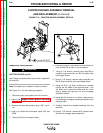
5. Disconnect motor leads 831 and 832 and tach leads
841, 844 and 847at their in-line connectors. See
the Wiring Diagram.
6. Using a 9/16” wrench, remove the bolt, lock wash-
er, flat washer and positive lead from the wire drive
assembly. Using pliers, remove the hose clamp
and flex hose from the wire drive assembly.
(Depends on the type of gun being used).
7. Rotate the adjustment arm assembly counterclock-
wise to release the tension on the idle arm.
8. Swing the idle arm up and away from the wire drive
assembly.
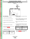
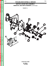
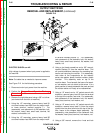
9. Remove the outer guide assembly from the wire
drive assembly by loosening the thumb screws
until the outer guide can be removed. Rotate the
molded keeper until the ears line up with the slots
on the drive roll, then pull the drive roll off the shaft
assembly. Now slide off the inner guide. See
Figure F.12.
10. Using a 9/16” wrench to remove nut that holds
molded drive roll shaft assembly to the wire drive
assembly. Remove the molded drive roll shaft
assembly form the wire drive assembly.
11. Using a 7/16” wrench remove panel covering the
gear.
12. Using a Phillips head screwdriver remove gear.
13. Using a Phillips head screwdriver, remove the 3
pan head screws and lock washers securing the
motor/gearbox assembly to the wire drive assem-
bly.
14. Grasp the motor/gearbox assembly and wiggle it
gently back and forth until it separates from the
wire drive assembly.
15. Using a 3/8” nut driver remove 6 nuts that hold
cover. Remove panel to expose drive motor.
WARNING