


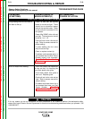

TROUBLESHOOTING & REPAIR
F-17 F-17
POWER MIG 350MP
Return to Section TOC Return to Section TOC Return to Section TOC Return to Section TOC
Return to Master TOC Return to Master TOC Return to Master TOC Return to Master TOC
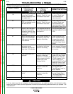
CHOPPER BOARD CAPACITOR DISCHARGE PROCEDURE (continued)
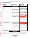
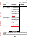
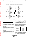
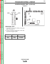
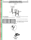
FIGURE F.1 – CHOPPER BOARD CAPACITOR TERMINAL DISCHARGE
PROCEDURE
ELECTRIC SHOCK can kill.
High voltage is present when input power is applied to
the machine.
Refer to Figure F.1.
1. Remove main input power supply to the machine.
2. Lift the hinged right side case cover.
3. Using the 3/8” nut driver, remove the bottom right
case cover.
4. Locate the Chopper Board with capacitors mount-
ed on the center of the machine base, right side.
See Figure F.1.
5. Using the resistor and jumper leads, CAREFULLY
discharge the capacitor terminals. There are 5
capacitors. NEVER USE A SHORTING STRAP
FOR THIS PURPOSE. DO NOT TOUCH THE
TERMINALS WITH YOUR BARE HANDS.
To discharge the capacitors, hold the jumper leads to
the following terminals for a minimum of 10 seconds
each. See Figure F.1 and the Wiring Diagram.
6. Using the volt/ohmmeter, check the voltage across
terminals B1 and B2 and B1 and B5 and B4 and
B5. Each reading should now be zero volts.
WARNING
Capacitors Terminals
C10 and C11 B1 and B2
C5 B1 and B5
C8 and C9 B4 and B5
300 CHOPPER
C12
+
C1
+
C4
C2
C3
+
+
++
_
_
_
_
C11
C10
C8
C9
B1 B4
B5
B6
B3
B2
B5
B2
B1
B3
B6
B4
J99