


TROUBLESHOOTING & REPAIR
F-46 F-46
POWER MIG 350MP
Return to Section TOC Return to Section TOC Return to Section TOC Return to Section TOC
Return to Master TOC Return to Master TOC Return to Master TOC Return to Master TOC
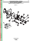
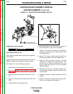
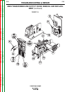
OUTPUT RECTIFIER
REMOVAL AND REPLACEMENT (continued)
washers holding the rectifier bracket to the machine
base.
10. Clear the leads and carefully remove the output
rectifier assembly.
11. With a 1/2” wrench, loosen the 3 nuts holding the
rectifier to its bracket.
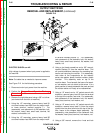
REPLACEMENT PROCEDURE
NOTE: When installing the output rectifier assembly,
apply a thin coating of Dow Corning #340 com-
pound to the electrical connections.
1. Fit the new output rectifier into its bracket.
2. Install the output rectifier. Fasten it to the machine
base with 4 lock washers and nuts.
3. Install heavy leads X1 and X2 to the terminals at the
top of the output rectifier. X1 mounts to the termi-
nal nearer to the chopper board assembly. Note
placement of fasteners as described above.
4. Install resistor R1.
5. Install heavy lead B5 and resistor lead 2520 to the
lower terminal, marked (+).
6. Install heavy lead B1 and resistor lead 2530 to the
upper terminal, marked (-).
7. Replace any cable ties removed for disassembly.
8. Install the case side panels.