


REMOVAL PROCEDURE
ELECTRIC SHOCK can kill.
High voltage is present when input power is applied to
the machine.
Note: Cut cable ties as needed to improve access.
PREPARATION
1. Disconnect main input power from the machine.
2. Remove the case side panels using a 3/8” nut dri-
ver.
3. Perform the Chopper Board Capacitor Discharge
Procedure.
4. Remove the case top using a 3/8” nut driver.
5. Remove gun.
6. Remove work lead from output stud.
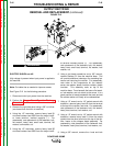
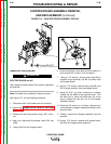
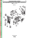
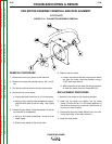
CASE FRONT ASSEMBLY REMOVAL
7. Remove the case front assembly as follows:
a. Using a phillips head screwdriver, remove the 2
screws holding the line switch to the case front.
b. Using a 5/16” nut driver, remove 10 screws
holding the case front to the to the machine
base and center assembly.
c. Lift the case front upward and forward slightly,
then disconnect plug J34 from the MSP3 mode
select panel. The case front assembly can now
be removed. See Figure F.14.
TROUBLESHOOTING & REPAIR
F-51 F-51
POWER MIG 350MP
Return to Section TOC Return to Section TOC Return to Section TOC Return to Section TOC
Return to Master TOC Return to Master TOC Return to Master TOC Return to Master TOC
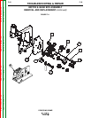
MAIN TRANSFORMER AND OUTPUT CHOKE REMOVAL AND REPLACE-
MENT (continued)
WARNING