


TROUBLESHOOTING & REPAIR
F-48 F-48
POWER MIG 350MP
Return to Section TOC Return to Section TOC Return to Section TOC Return to Section TOC
Return to Master TOC Return to Master TOC Return to Master TOC Return to Master TOC
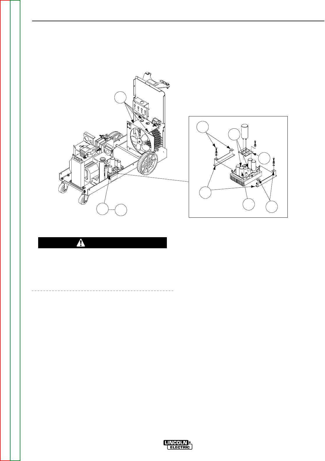
CHOPPER BOARD ASSEMBLY REMOVAL
AND REPLACEMENT (continued)
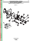
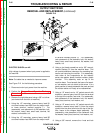
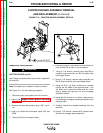
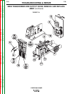
FIGURE F.13 – CHOPPER BOARD ASSEMBLY DETAILS
REMOVAL PROCEDURE
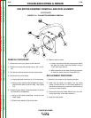
ELECTRIC SHOCK can kill.
High voltage is present when input power is applied to
the machine.
Note: Cut cable ties as needed to improve access.
See Figure F.13 for the following procedure.
1. Disconnect main input power from the machine.
2. Perform the Chopper Board Capacitor Discharge
Procedure.
3. Remove the case side panels using a 3/8” nut dri-
ver.
4. Label and disconnect thermostat leads 503 and
503A.
5. Unplug J99 from the chopper board.
6. Disconnect lead 607 from terminal B8 and lead 613
from terminal B7 at their in-line connectors.
7. Using a 7/16” wrench, remove heavy lead B8 (to
negative output terminal) and B2 (to choke) from
the chopper board.
8. Using a 7/16” wrench, remove heavy leads B1 and
B5 (to output rectifier) from the chopper board.
9. Using the 5/16” nut driver, remove the 4 screws
holding the fan baffle to the machine base. This
will allow you to move the baffle back out of the
way to access the right rear nut on the chopper
assembly bracket.
10. Using the 3/8” wrench or nut driver, remove the 4
nuts holding the chopper assembly brackets to the
machine base.
11. Carefully remove the chopper assembly from the
machine.
12. Using a 7/16” wrench, remove the 2 support brack-
ets from the chopper board assembly.
9
4
6
Leads B8 & B7
(other side of chopper board)
12
10
7
23D
8
12
WARNING