


Return to Section TOC Return to Section TOC Return to Section TOC Return to Section TOC
Return to Master TOC Return to Master TOC Return to Master TOC Return to Master TOC
TROUBLESHOOTING & REPAIR
F-19 F-19
POWER MIG 350MP
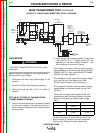
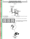
MAIN TRANSFORMER TEST (continued)
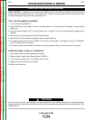
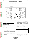
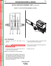
FIGURE F.2 – MAIN TRANSFORMER TEST POINT LOCATIONS
PROCEDURE
The ON/OFF POWER SWITCH will be "hot" during
these tests.
NOTE: Secondary voltages will vary proportionately
with the primary input voltage.
1. Disconnect the main input power supply to the
machine.
2. Perform the Case Cover Removal procedure.
3. Remove the tool tray with a 5/16” nut driver (3
screws).
TEST INPUT VOLTAGE TO THE MAIN TRANS-
FORMER PRIMARY WINDING:
4. Confirm the reconnect panel is connected properly
for the correct voltage. See reconnect panel con-
nection diagram located on back of machine above
reconnect door.
5. Test for correct input voltage between L1 lead at the
LINE SWITCH to L2. Voltage tested will vary
depending on the input voltage connection. See
Wiring diagram for test point locations.
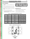
* If the voltage is incorrect, check for loose or broken
leads between the reconnect panel and the ON/OFF
POWER SWITCH. Also, test the ON/OFF POWER
SWITCH for proper operation.
* If the voltage is correct, check for the same voltage
at H1 and H4 and at the bottom of the LINE
SWITCH with the switch in the ON position.
* If the voltage is incorrect, check for loose or broken
leads between the reconnect panel and the LINE
SWITCH.
* If the correct voltage is being applied to the main
transformer primary winding, proceed to the table
below for the secondary winding output voltage
tests.
WARNING
5
0
w
a
t
t
s
5
0
0
o
h
m
s
2520
2530
R1
+
2400/100
+
-
57 VAC
-
+
CONTROL RECTIFIER
80 VDC
OUTPUT
RECTIFIER
MAIN
TRANSFORMER
X6X5
X4X3
X1
X2
30 VAC115 VAC
LOCATED ON
TRANSFORMER
BAFFLE
LOCATED ON FRONT
OF MACHINE'S BASE
LOCATED ON
MACHINE'S BASE
(STORAGE
COMPARTMENT SIDE)
H1
H4
H1
(SHOWN
CONNECTED
FOR 230V)
H4
H3
H2H5
L2
L1
G
B
W
H1
L1
L2
H4
H1
H4
H3
H5
H2
H1
LINE
SWITCH
RECONNECT PANEL
LOCATED NEXT TO
MAIN TRANSFORMER
(ON WIRE DRIVE SIDE)
LOCATED ON
CHOPPER BOARD
ASSEMBLY
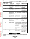
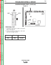
Leads
X1-X2
X3-X4
X5-X6
Description
Power to output
rectifier
Power to fan motor &
115 VAC receptacle
Power to control
rectifier
Expected Voltage
57 VAC
115 VAC
30 VAC
If the correct voltage is being applied to the main
transformer and one or more of the secondary volt-
ages is missing or incorrect, the main transformer
may be faulty. Replace the main transformer.