


POWER MIG 350MP
Return to Section TOC Return to Section TOC Return to Section TOC Return to Section TOC
Return to Master TOC Return to Master TOC Return to Master TOC Return to Master TOC
B-5
B-5
OPERATION
SETTING AND CONFIGURING THE POWER
MIG 350MP FOR WELDING
• Check that the electrode polarity is correct for the process
and turn the Power Switch to the "ON" position. After the
"boot-up" period (approximately 20 seconds), the Power
MIG 350MP will default to the last preset weld mode that
was active when the machine was powered down. The
Multi-Process Panel defaults with the "Weld Mode" active.
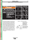
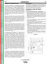
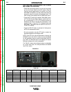
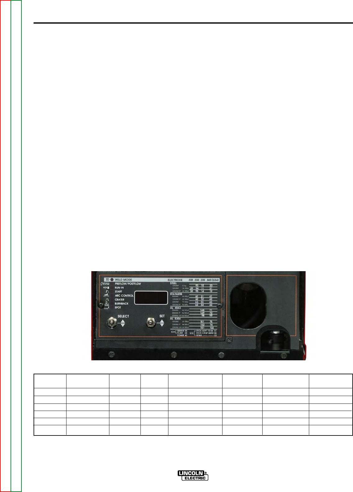
• Toggle the SET switch to the desired "Weld Mode" opera-
tion. The Multi-Process Meter displays a weld mode num-
ber corresponding to a CC or CV welding process as
detailed by the chart on the right side of the panel. In the
example shown in Figure B.2 “3” is displayed above the
SET switch. This means that the machine is set for CC-
GTAW (TIG) welding.
• Toggle the SELECT switch to activate the "weld parame-
ters" for the selected weld mode.
• Set each parameter using the SET switch to adjust the
parameter displayed on the display meter.
NOTE: If the LED next to the weld parameter is flashing, the
WFS/AMP and/or the Volt/Trim values can also be adjusted
for that parameter using the control knobs below each dis-
play meter. An LED below each of the displays will also be
flashing to indicate which value is adjustable.
The Table B.1 shows which weld parameters are adjustable
for a given weld mode. The weld parameters are detailed
later in this section.
PREFLOW / RUN IN START ARC CONTROL CRATER BURNBACK SPOT
POSTFLOW
CC-STICK ----- ----- Yes Yes ----- ----- -----
CC-GTAW Yes ----- Yes ----- ----- ----- -----
CV-FCAW ----- Yes Yes Yes Yes Yes Yes
CV-GMAW Yes Yes Yes Yes Yes Yes Yes
CV-GMAW-P
Yes Yes Yes Yes Yes Yes Yes
POWER Yes Yes Yes Yes Yes Yes Yes
3
FIGURE B.2
TABLE B.1