


8
WIRE CONNECTIONS
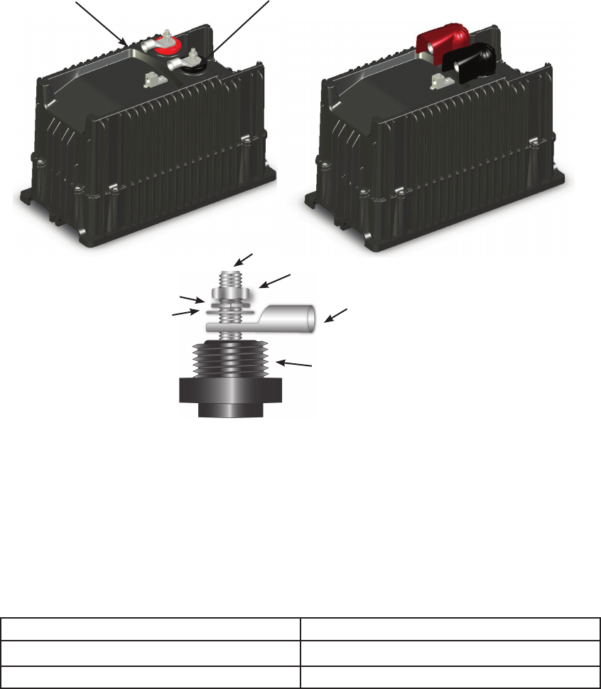
DC Wiring
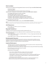
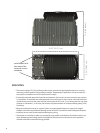
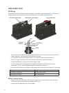
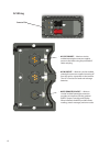
TheInverterusesDCbrassbatteryterminalswith8Mx1.00stainlesssteelthreadedstuds.Youcanaccess
the terminals by removing the four screws that attach the DC cover plate, and pulling it o.
Red terminal=battery positive
Battery terminal covers
Black terminal = battery negative
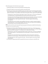
Never install extra washers or any other hardware between the terminal mounting surface and the •
battery cable lug—the connection must be direct and secure.
FortheInvertermodelOBX-IC2024S-120/60,a175-ampDCbreakerisrecommended.Ifa•
DC fuse is used, it should be a Class T fuse and must not exceed a rating of 300 amps.•
Always install breakers or fuses on the positive battery cable.•
It is recommended to twist the positive and negative conductors around each other during •
installation. This is to reduce EMI (electromagnetic interference) emissions.
Use torque values from the chart below for tightening battery connections and Inverter DC connections.•
Connection Torque
DC Battery Connections to 10 foot-lbs/13.6 Nm
Inverter’s DC terminals to5foot-lbs/5.8Nm
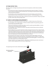
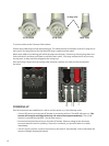
Battery Terminal Covers
The caps are made of sti plastic with a snap-on design; remove them carefully using a at-blade •
screwdriver inserted into the slots on the sides of each cover.
Always keep the battery terminal covers installed.•
Battery Cable Lug
Lock Washer
Flat Washer
Nut
Insulator
Stud