


13
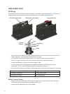
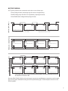
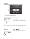
Follow these steps to wire the Inverter to your system:
Open all DC breakers or remove any fuses before connecting wiring. 1.
Open all AC breakers or remove any fuses before connecting wiring.2.
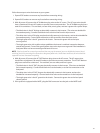
With all power o, connect the AC IN Maxicon plug wires to the AC source. The AC input wires should 3.
have a (maximum) 30-amp AC breaker to provide overcurrent protection. The AC IN Maxicon plug has a
total of six conductors. Two are black, two are white, one is green, and one is green with a yellow stripe.
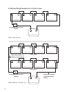
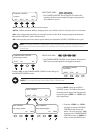
The black wires in the AC IN plug are electrically common in the Inverter. (The wires are doubled for •
increased ampacity.) Connect both black wires to the hot line from the input source.
The white wires in the AC IN plug are also electrically common in the Inverter, and are also doubled for •
increased ampacity. Connect both white wires to the neutral line from the input source.
The single green wire is the AC ground to the chassis. Connect the green wire to the input •
source ground.
The single green wire with a yellow stripe establishes the Inverter’s switched connection between •
neutral and ground. Connect the green/yellow wires to the input source ground if the installation’s
load panel does not have a neutral-ground bond of its own.
NOTE: If the load panel has a neutral-ground bond that may not be removed, you must disable the Inverter’s bond-
switching function by removing the connection to the green/yellow wire. Under these conditions, this wire should be
capped o and not connected to anything.
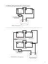
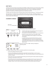
With all power o, connect the AC OUT Maxicon plug wires to the AC source. The AC output wires 4.
should have a (maximum) 30-amp AC breaker to provide overcurrent protection. The AC OUT Maxicon
plug has a total of ve conductors. Two are black, two are white, and one is green.
The black wires in the AC OUT plug are electrically common in the Inverter. (The wires are doubled •
for increased ampacity.) Connect both black wires to the breaker, or to the hot connection on the
load panel.
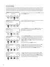
The white wires in the AC OUT plug are also electrically common in the Inverter, and are also •
doubled for increased ampacity. Connect both white wires to the neutral bus on the load panel.
The single green wire is the AC ground to the chassis. Connect the green wire to the load panel •
chassis ground.
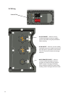
IfthesystemisequippedwithaMATE,plugtheRJ45connectorintothejackontheMATEitself.5.