


14
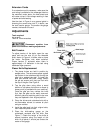
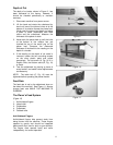
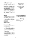
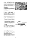
To adjust the height of the outfeed roller, loosen
the nut (G, Fig. 16), place a wrench upon the
flats of the screw (H, Fig. 16) and rotate the
screw as needed. Re-tighten the nut (G, Fig. 16)
when finished.
To adjust the tension of the outfeed roller, turn
the lock nut (F, Fig. 16) as needed.
Do not over-compress the
spring on the outfeed roller! Carefully
observe the same instructions concerning
the infeed roller height and tension
adjustments, on pages 11-12.
If the feed rollers are not able to be adjusted to
the proper tension, they should be replaced.
Leveling Cutterhead with Bed
The cutterhead has been leveled with the
surface of the planer bed at the factory.
However, should future adjustment be needed,
proceed as follows:
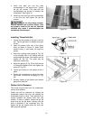
1. Place a bed and feed roll gauge (or wood
block) beneath one end of the cutterhead.
Crank the planer bed up until the cutterhead
is just touching the gauge, and check the
measurement. Move gauge to the opposite
end and check.
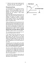
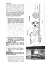
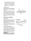
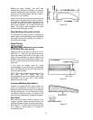
2. If the cutterhead is not level with the table,
remove the drive belts, and the four hex
head screws (A, Fig. 17) holding the
platform to the stand. Turn the head
assembly over to reach the sprocket
adjustments underneath the platform.
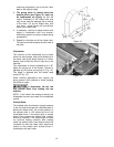
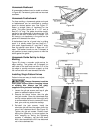
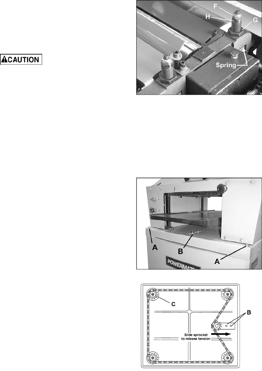
3. Loosen the cap screws (B, Fig. 17 & 18)
near the idler sprocket to relieve tension on
the chain. Remove chain from sprocket on
the end that needs adjustment.
4. Turn the sprocket (C, Fig. 18) to raise or
lower that edge of the table. NOTE: This
adjustment is sensitive and it should not be
necessary to turn the sprocket more than
one or two teeth.
5. After checking with the gauge to make sure
the adjustments are correct, place chain
back on sprocket, re-tension idler sprocket,
tighten cap screws (B, Fig. 18) and secure
head assembly back on to the stand with
the four hex head screws (A, Fig. 17).
Figure 16
Figure 17
Figure 18