8
Electricals should be installed so that the
y
are
protected from damage and exposure. Be sure
to properly ground the machine frame.
Exposed metal parts, such as the bed surface,
have been given a protective coating at the
factory. This should be removed with a soft rag
and kerosene or a good commercial solvent.
Do not use an abrasive pad.
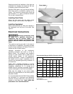
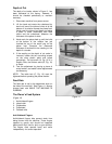
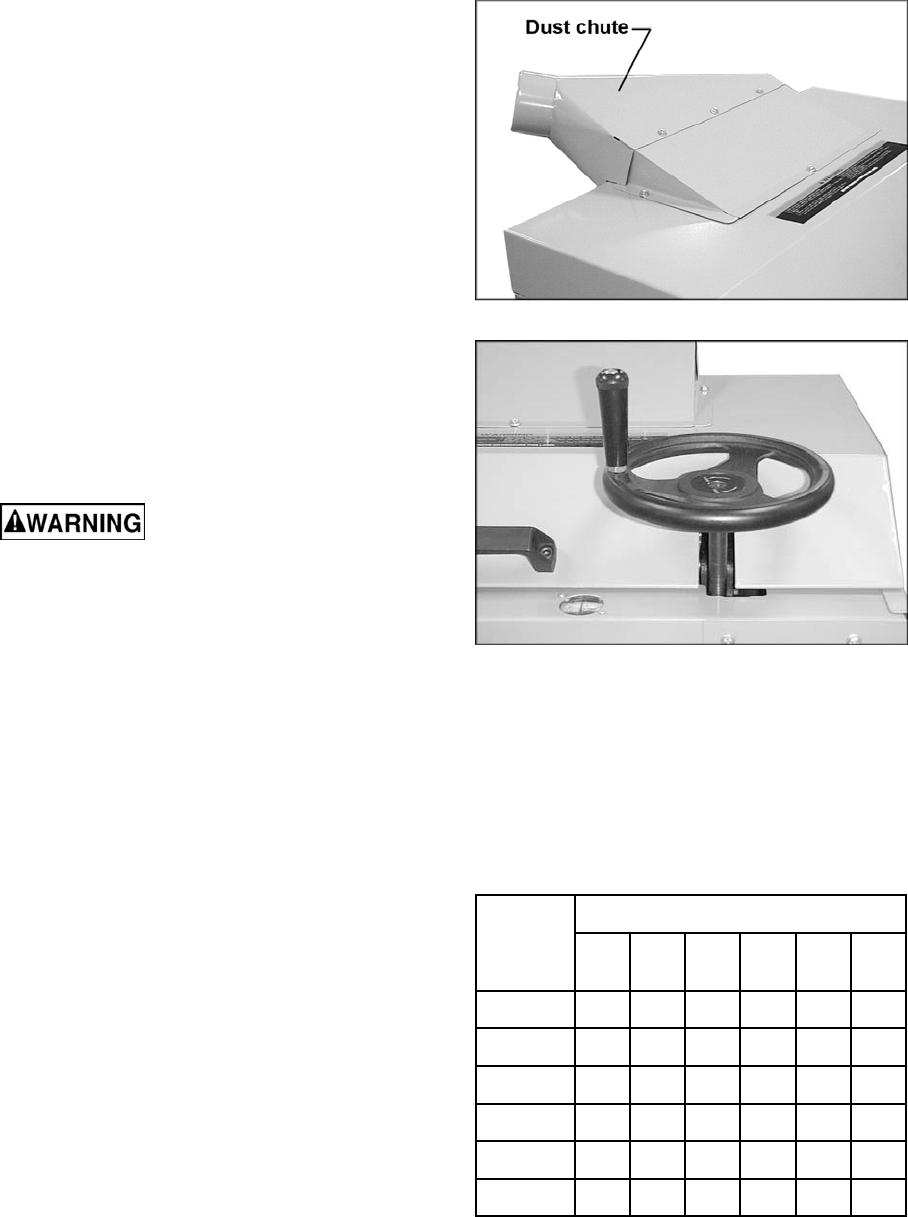
Installing Dust Chute
Mount the dust chute with the washer head
screws, using a 10mm wrench. See Figure 2.
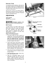
Installing Handwheel
Mount the handwheel by fitting the notches in
the handwheel over the pins on the shaft. See
Figure 3.
Electrical Connections
Electrical connections must
be made by a qualified electrician in
compliance with all relevant codes. This
machine must be properly grounded to help
prevent electrical shock and possible fatal
injury.
This machine must be grounded. In the event of
a malfunction or breakdown, grounding provides
a path of least resistance for electric current to
reduce the risk of electric shock.
Improper connection of the equipment-
grounding conductor can result in a risk of
electric shock. The conductor with insulation
having an outer surface that is green with or
without yellow stripes, is the equipment-
grounding conductor. If repair or replacement of
the electric cord or plug is necessary, do not
connect the equipment-grounding conductor to
a live terminal.
Check with a qualified electrician or service
personnel if the grounding instructions are not
completely understood, or if in doubt as to
whether the tool is properly grounded. Repair or
replace a damaged or worn cord immediately.
Make sure the voltage of your power supply
matches the specifications on the motor plate of
the planer-molder.
It is recommended that the PM15 Planer-Molder
be connected to a grounded and dedicated,
minimum 40 amp circuit with a 40 amp circuit
breaker or time delay fuse. Local codes take
precedence over recommendations.
Figure 2
Figure 3
Recommended Gauges (AWG) of Extension Cords
Amps
Extension Cord Length *
25
feet
50
feet
75
feet
100
feet
150
feet
200
feet
< 5 16 16 16 14 12 12
5 to 8 16 16 14 12 10 NR
8 to 12 14 14 12 10 NR NR
12 to 15 12 12 10 10 NR NR
15 to 20 10 10 10 NR NR NR
21 to 30 10 NR NR NR NR NR
*based on limiting the line voltage drop to 5V at 150% of the
rated amperes.
NR: Not Recommended.
Figure 4


