


19
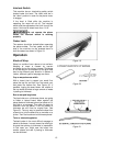
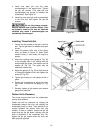
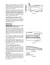
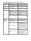
4. Install one steel
g
ib and the steel
counterweight in the second slot. Tighten
the gib set screws. (The steel gib and
counterweight are ground to balance the
cutterhead.) See Figure 30.
5. Install the other steel gib and counterweight
in the third slot and tighten the gib set
screws.
Do not interchange counter-
weights between sets of pattern knives. They
are properly sized for the one set. Machine
vibration may result if counterweights are
accidentally interchanged.
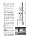
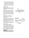
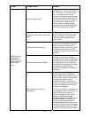
Installing Three-Knife Set
1. Loosen the set screws on the gib in the first
slot. Tap the gib down to release the planer
knives.
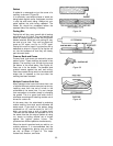
2. Insert the pattern knife next to the planer
knife, as shown in Figure 31. Note: Small
molder knives (1” and under) will require a
spacer.
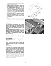
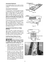
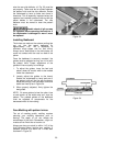
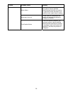
3. Mount the molding cutter gauge (A, Fig. 32)
to the theaded hole in the casting with the
socket head cap screw, lock washer and flat
washer (B, Fig. 32). The guide may be
attached to either side.
4. Adjust the gauge (A, Fig. 32) so that the end
of it meets the pattern knife, then tighten the
screw (B, Fig. 32).
5. Tighten gib screws to hold pattern knife in
place.
6. Rotate the cutterhead and adjust the other
two knives to meet the the gauge (A, Fig.
32).
7. Securely tighten all gib screws and remove
gauge from machine.
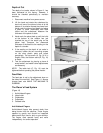
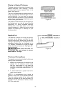
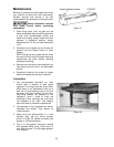
Pattern Knife Clearance
The knives should clear both the chipbreaker
and the chip deflector.
Check the knife for clearance by rotating the
chipbreaker toward the knife and rotating the
cutterhead slowly by hand. There should be no
contact between the pattern knife and chip
breaker. If there is contact, loosen the gib set
screw and tap the gib down, making sure the
knife is bottomed in the cutterhead slot. Re-
tighten the gib set screws when the knife has
been properly adjusted.
Figure 30
Figure 31
Figure 32