


For Machines Mfg. Since 3/11 16-Speed Gearhead Lathe
-27-
PREPARATION
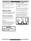
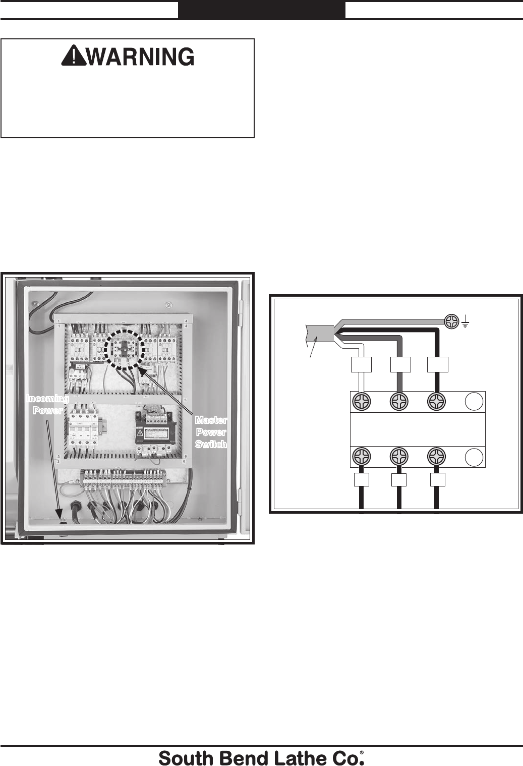
L3
L2
L1
To Power
Supply
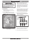
Hot
MASTER
POWER SWITCH
Hot
Hot
Ground
Figure 27. Power connection at master power switch.
4. Make sure the wires have enough slack so
that they do not bind at the terminals.
5. Close and lock the main electrical box door.
Connecting Power
1. Make sure the master power switch is
turned to the OFF position, then open the
electrical cabinet door.
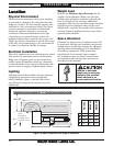
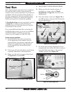
2. Refer to Figure 26 to identify the master
power switch and the hole at the bottom of
the electrical cabinet for the incoming power.
Electrocution could occur if you attempt this
procedure with the power wires connected to
the power source. The incoming power wires
must be disconnected from power before
performing this procedure.
Figure 26. Location to connect power inside main
electrical cabinet.
Master
Power
Switch
Incoming
Power
Note: For the Model SB1053, thread the
power cord through an approved and
properly sized strain relief as it enters the
electrical cabinet. The strain relief must be
tightened against the outer jacket of the
cord; however, avoid over-tightening the
strain relief or it may crush the cord and
cause a short.
Test the strain relief to ensure it is properly
tightened by pulling the cord from outside
the cabinet with light-to-moderate force.
When the strain relief is properly tightened,
the cord will not move inside the cabinet.
3. Connect the incoming hot wires to the
upper master power switch terminals and
the ground wire to the ground terminal, as
illustrated in Figure 27.