


SERVICE
For Machines Mfg. Since 3/11 16-Speed Gearhead Lathe
-77-
SERVICE
Gib Adjustment
The goal of adjusting the gib screws is to remove
sloppiness or "play" from the ways without over-
adjusting them to the point where they become
stiff and difficult to move.
In general, loose gibs cause poor finishes and
tool chatter; however, over-tightened gibs cause
premature wear and make it difficult to turn the
handwheels.
Important: Before adjusting the gibs, loosen the
locks for the device so that the gibs can freely
slide during adjustment, then lubricate the ways.
The gibs are tapered and held in position by a
screw at each end. To adjust the gib, turn one
screw
1
⁄4 turn clockwise and the other screw
1
⁄4
turn counterclockwise, so both screws move in
the same direction and the same amount. Test
the feel of the sliding component by turning
the handwheel, and adjust the gib screws as
necessary to make it tighter or looser.
The gib adjustment process usually requires
some trial-and-error. Repeat the adjustment
process as necessary until you find the best
balance between loose and stiff movement. Most
machinists find that the ideal gib adjustment is
one where a small amount of drag or resistance
is present yet the handwheels are still easy to
move.
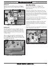
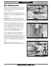
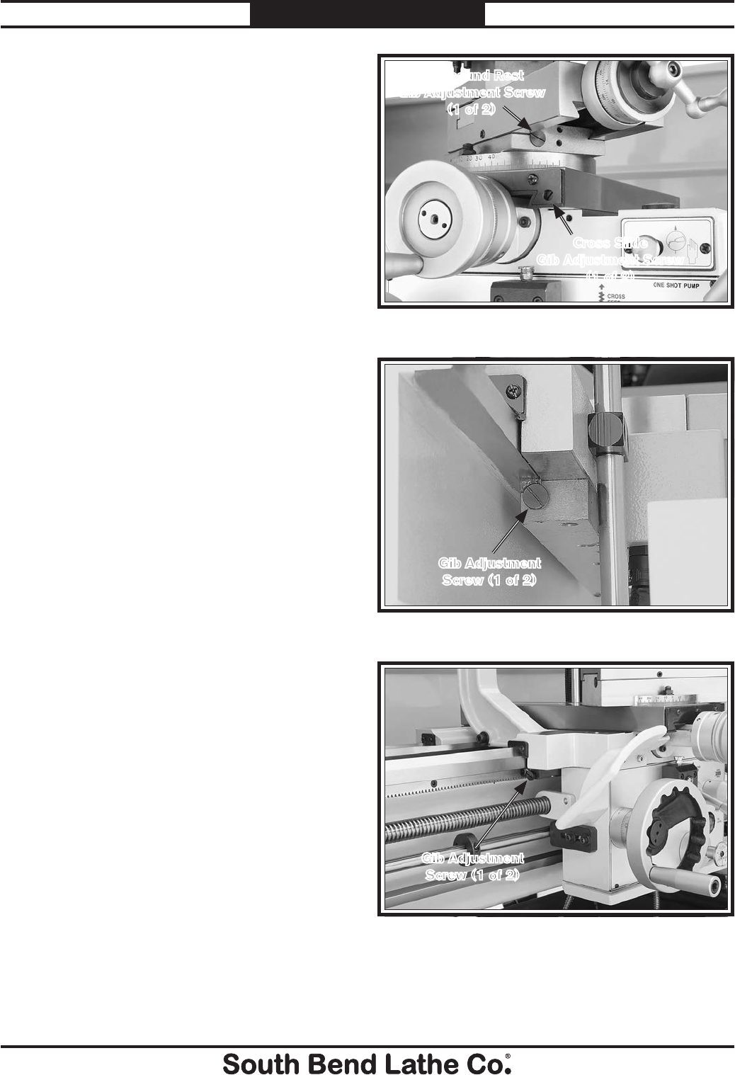
Figures 124–128 show the location of the
adjustment screws for each gib on this machine.
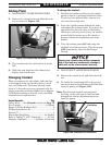
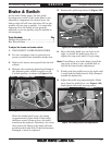
Figure 124. Compound and cross slide gib adjustment
screws.
Compound Rest
Gib Adjustment Screw
(1 of 2)
Cross Slide
Gib Adjustment Screw
(1 of 2)
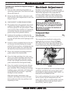
Figure 125. One of two rear saddle gib adjustment
screws.
Gib Adjustment
Screw (1 of 2)
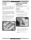
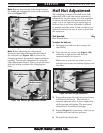
Figure 126. Front saddle gib adjustment screw.
Gib Adjustment
Screw (1 of 2)