


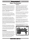

For Machines Mfg. Since 3/11 16-Speed Gearhead Lathe
-7-
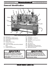
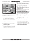
INTRODUCTION
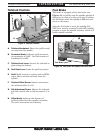
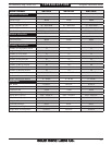
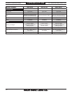
A. 4-Position Tool Post Lever: Locks the tool
holder in four possible positions.
B. Compound Rest Handwheel: Moves the
cutting tool back and forth relative to
the workpiece. Includes an indirect-read
graduated dial, which represents actual tool
movement.
C. Coolant Valve Lever: Controls the flow of
coolant from the nozzle.
D. One-Shot Oiler: Draws oil from the apron
reservoir and lubricates the bed ways
underneath the saddle.
E. Carriage Lock Bolt: Secures the carriage in
place for greater rigidity and accuracy when
using the cross slide or compound rest for
machining operations.
Figure 8. Carriage controls.
A
C
B
E
D
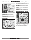
F
G
I
J
K
L
N
M
H
F. Thread Dial: Indicates when to engage the
half nut during inch threading operations.
G. Spindle ON/OFF Lever: Starts, stops and
reverses direction of spindle rotation.
H. Thread Dial Chart: For each inch thread,
displays which number on the thread dial to
engage the half nut.
I. Half Nut Lever: Engages and disengages the
half nut for threading operations.
J. Quick-Change Feed Direction Knob: Changes
direction of carriage feed or the cross slide
feed without having to stop the lathe and
move the headstock feed direction lever.
K. Feed Control Lever: Engages and disengages
the cross slide or carriage feed.
L. Carriage Handwheel: Moves the carriage
manually along the bed.
M. Apron: Houses the carriage gearing and
controls.
N. Cross Slide Handwheel: Moves the cross
slide toward or away from the workpiece.
Includes a direct-read graduated dial, which
represents half the amount of tool movement
and the total amount of material removed
from the diameter of the workpiece.
Carriage Controls