


For Machines Mfg. Since 3/11 16-Speed Gearhead Lathe
-73-
MAINTENANCE
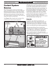
To change the coolant:
1. Position the coolant nozzle over the splash
guard so that it is pointing behind the lathe.
If you have the optional hose, connect it to
the end of the nozzle now.
2. Place the 5-gallon bucket behind the lathe
and under the coolant nozzle. If you have the
optional hose, place the hose in the bucket.
Otherwise, you may need to have an another
person hold the bucket up to the nozzle to
prevent coolant from splashing out of the
bucket.
3. Turn the coolant pump ON and pump the
old fluid out of the reservoir. Turn the pump
OFF immediately after the fluid stops
flowing.
Adding Fluid
1. DISCONNECT LATHE FROM POWER!
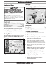
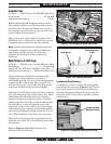
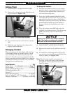
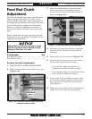
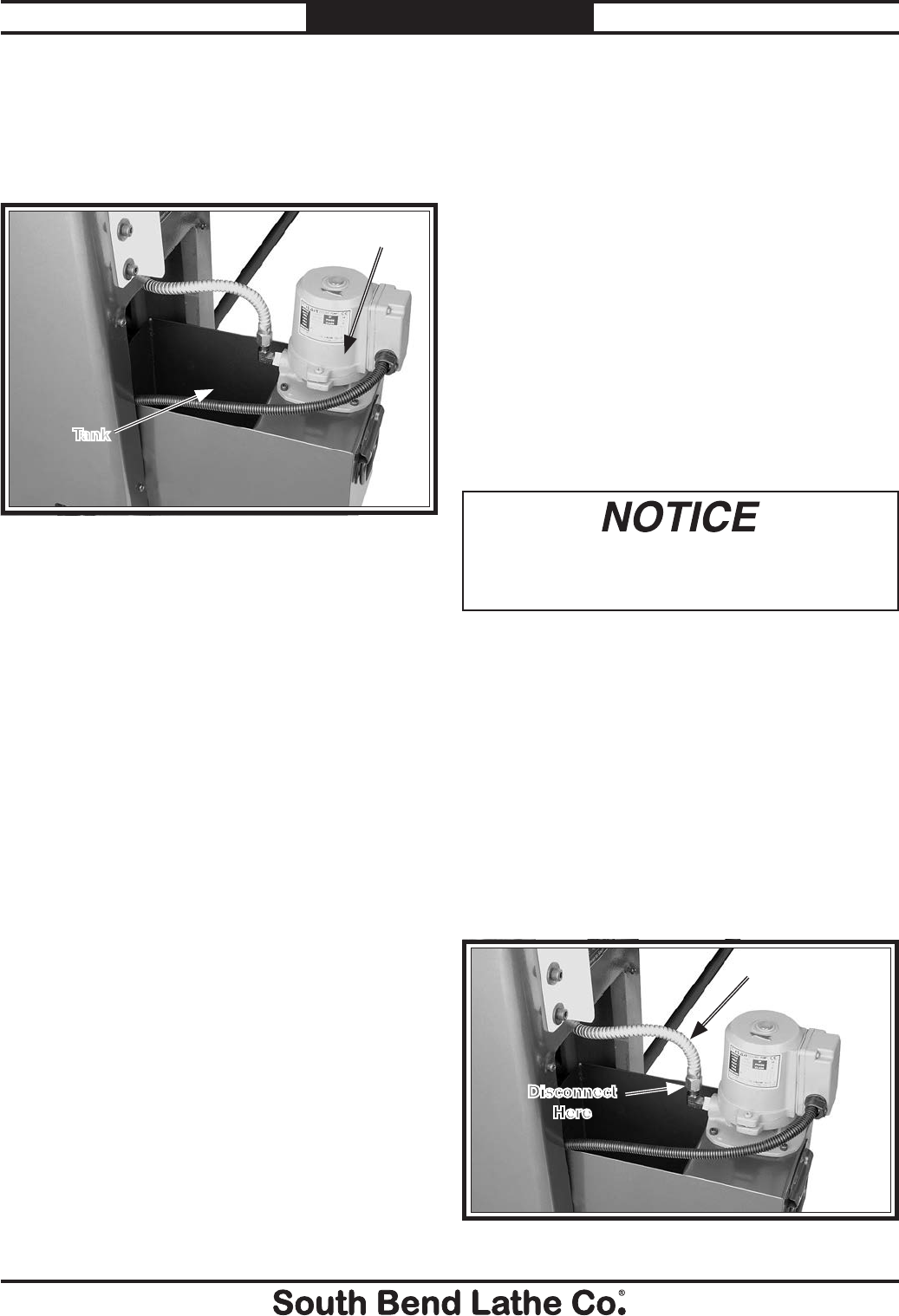
2. Remove the vented cover and slide the tank
out, as shown in Figure 119.
Figure 119. Coolant tank and pump.
Pump
Running the coolant pump without adequate
fluid in the tank may permanently damage it,
which will not be covered under warranty.
3. Pour coolant into the tank until it is nearly
full.
4. Slide the tank back into the cabinet and
replace the vented cover.
Changing Coolant
When you replace the old coolant, take the time
to thoroughly clean out the chip drawer, catch
tray, and fluid tank. The entire job only takes
about a
1
⁄2 hour when you are prepared with the
proper materials and tools. Make sure to dispose
of old fluid according to federal, state, and fluid
manufacturer's requirements.
Items Needed: Qty
Safety Wear ......See Hazards section on Page 72
New Coolant ............................................ 3 Gallons
Empty 5-Gallon Bucket w/Lid .............................. 2
Phillips Screwdriver #2 ........................................1
Wrench
3
⁄4" .............................................................1
Disposable Shop Rags ........................... As Needed
Hose or Tubing
5
⁄8" x 60" (Optional) ........... 1 Piece
Magnets (Optional) ...............As Many As Desired
Tank
4. DISCONNECT LATHE FROM POWER!
5. Remove the vented cover and slide the tank
out.
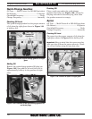
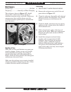
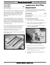
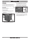
6. To enable the remaining fluid to be poured
out in the next step, disconnect the fluid hose
from the pump (see Figure 120).
Note: The electrical conduit was purposely
left long, so the tank can be removed and
dumped out without disconnecting wires
from the pump.
Figure 120. Fluid hose and connection.
Fluid Hose
Disconnect
Here