


For Machines Mfg. Since 3/11 16-Speed Gearhead Lathe
-85-
SERVICE
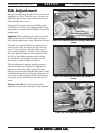
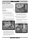
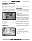
The gap insert directly under the spindle (see
Figure 146) can be removed to create additional
space for turning large diameter parts.
The gap insert was installed, then ground flush
with the bed at the factory to ensure a precision
fit and alignment. Therefore, if the gap insert is
removed, it may be difficult to re-install with the
same degree of accuracy.
Gap Insert Removal &
Installation
Tools Needed: Qty
Hex Wrenches 6mm ..............................................1
Hex Wrench 8mm .................................................1
Wrench 17mm .......................................................1
Dead Blow Hammer ..............................................1
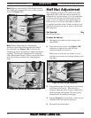
Gap Removal
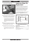
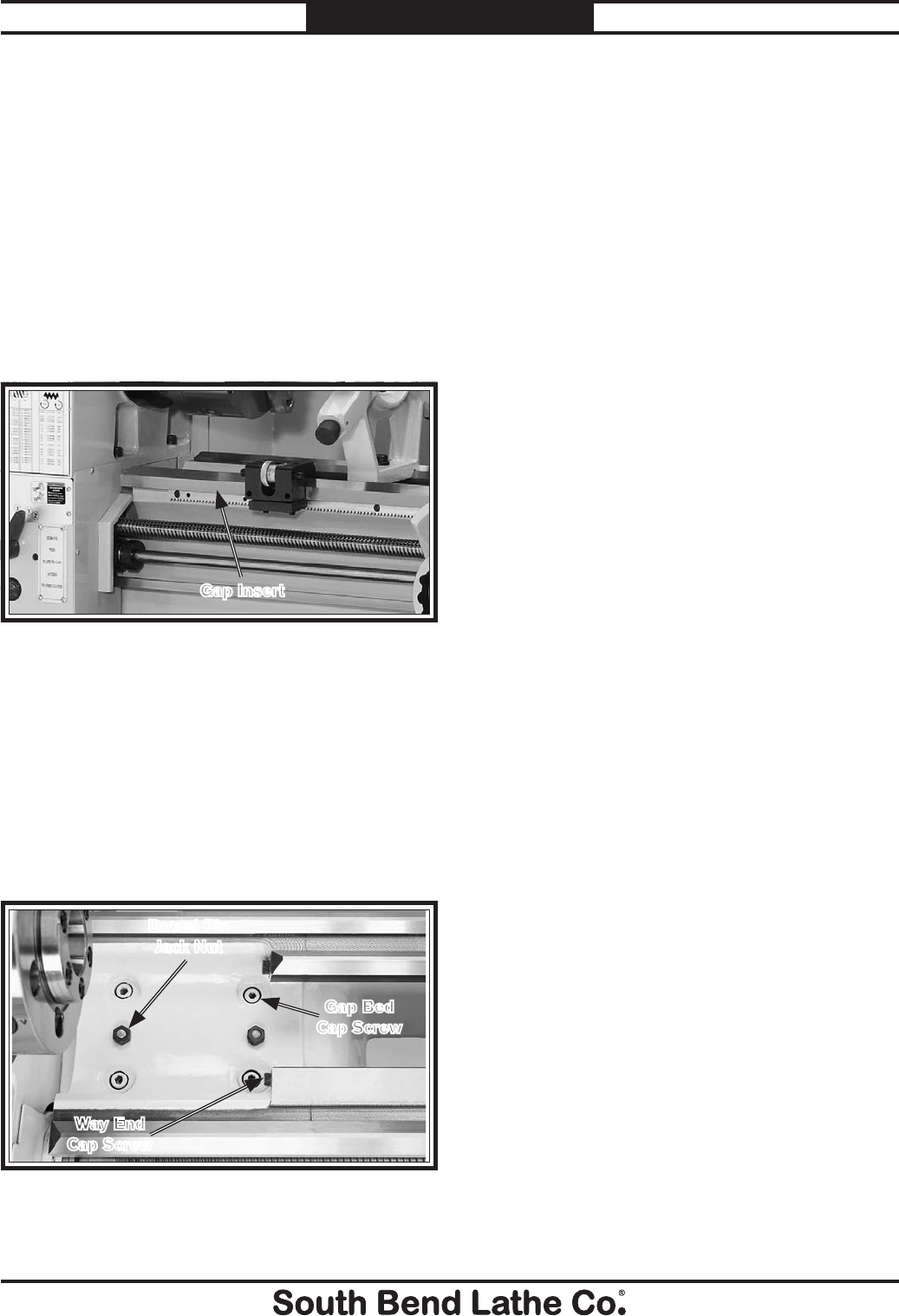
1. Remove the four gap-bed cap screws, shown
in Figure 147.
Figure 146. Gap insert.
Gap Insert
Figure 147. Fasteners holding gap in place.
Gap Bed
Cap Screw
Way End
Cap Screw
Dowel Pin
Jack Nut
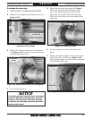
2. Remove the two way-end cap screws.
3. Tighten the two dowel-pin jack nuts until the
pins are pulled free from the gap insert.
4. Tap the outside of the gap insert with a dead
blow hammer to loosen it, then remove it.
Gap Installation
1. Use mineral spirits and a clean lint-free rag
to clean the mating surfaces of the gap, bed,
and ways. If necessary, stone the mating
surfaces to remove scratches, dings, or burrs.
2. Wipe a thin layer of light machine oil on the
mating surfaces.
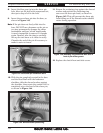
3. Place the gap insert into the gap and use a
dead-blow hammer to align the insert with
the lathe bed.
4. Back off the dowel pin jack nuts, and lightly
tap the dowel pins back into their respective
holes until they are seated. This process will
further help align the gap insert and bed
mating surfaces.
5. Install all fasteners and lightly snug them in
place.
6. Mount a dial indicator with a magnetic base
to the top of the saddle to indicate alignment.
7. First test the peak of the two prisms of the
gap insert that the saddle rides on, then test
the flanks of the prisms.
8. Tighten the gap bed cap screws in an
alternating manner and tap the side of the
gap insert into alignment.
9. Inspect the gap alignment 24 hours later
to make sure the gap is still aligned. If
necessary, loosen the gap bed cap screws and
repeat Steps 7–8 until the insert is properly
aligned.