


For Machines Mfg. Since 3/11 16-Speed Gearhead Lathe
-83-
SERVICE
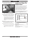
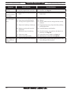
4. Put on safety glasses.
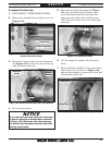
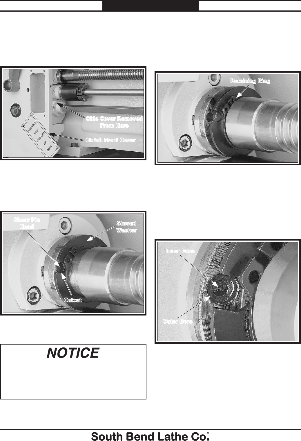
Figure 140. Shroud washer and shear pin alignment.
Cutout
Shear Pin
Head
Shroud
Washer
3. Rotate the shroud washer on the leadscrew
(see Figure 140) so that the cutout lines up
with the shear pin head.
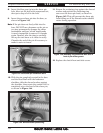
5. Move the retaining ring shown in Figure
141 away from the shroud washer, then
move the shroud washer away from the
shear pin and against the retaining ring.
This will create room for you to remove the
shear pin.
Figure 141. Shear pin access.
Retaining Ring
6. Use the magnet to remove the shear pin
head.
7. Rotate the lathe spindle to line up the inner
and outer bores, as shown in Figure 142,
and use the magnet to remove the other half
of the broken shear pin.
Figure 142. Shear pin bores aligned.
Outer Bore
Inner Bore
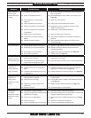
If you fabricate your own shear pin, make sure
to use the material and dimensions specified
in Figure 138. Otherwise, the shear pin may
not provide the intended protection and lathe
damage could result.
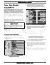
To replace the shear pin:
1. DISCONNECT LATHE FROM POWER!
2. Remove the clutch front and side covers (see
Figure 139).
Figure 139. Location of clutch front cover (side cover
removed for photo clarity).
Clutch Front Cover
Side Cover Removed
From Here