


For Machines Mfg. Since 3/11 16-Speed Gearhead Lathe
-5-
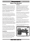
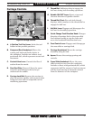
INTRODUCTION
Refer to Figures 2–9 and the following
descriptions to become familiar with the features
and basic controls of this lathe. This knowledge
will be necessary to properly set up the lathe for
the test run and spindle break-in.
Controls &
Components
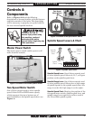
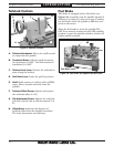
Figure 2. Location of the master power switch.
Main Power
Switch
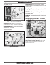
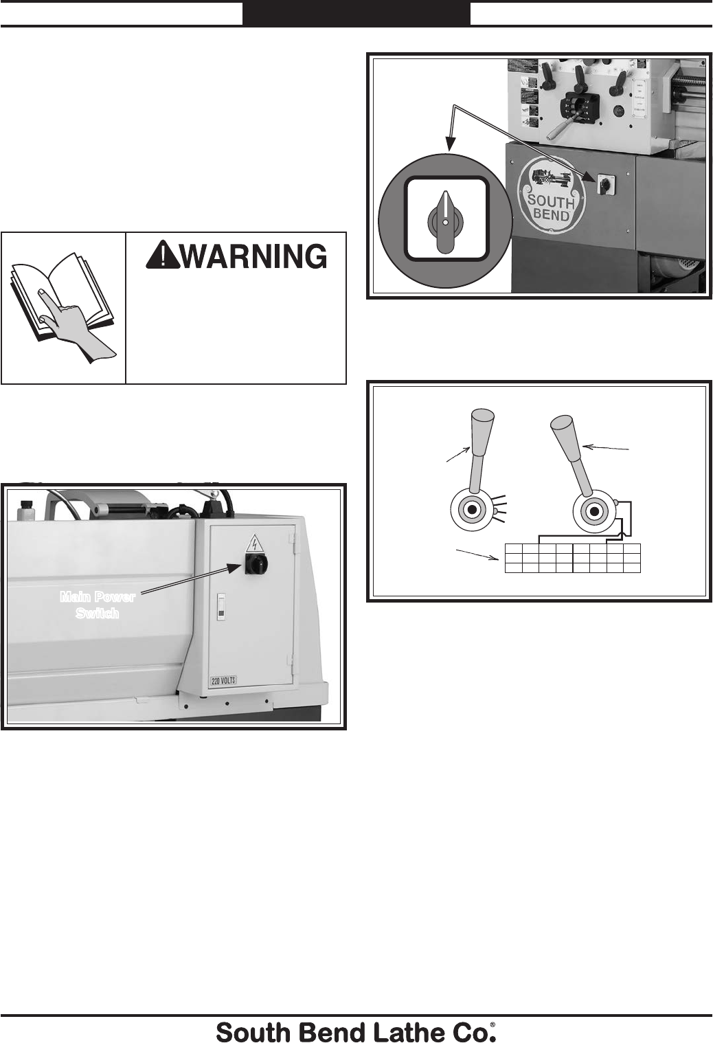
Two-Speed Motor Switch
One of three controls used to select spindle
speed. Select LOW or HIGH motor speeds,
which represent the top or bottom row of
speed available on the spindle speed chart (see
Figure 4).
Master Power Switch
The master power switch enables power to all
lathe electrical controls.
To reduce the risk of
serious injury when using
this machine, read and
understand this entire
manual before beginning any
lathe operations.
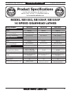
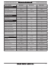
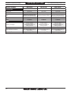
Spindle Speed Levers & Chart
Figure 4. Spindle speed chart.
C
B
A
D
10006253752451651006040
2000125075049033020012080
DCBADCBA
Spindle
Speed
Lever
Spindle
Range
Lever
Speed
Chart
Spindle Speed Lever: One of three controls used
to select spindle speed. Selects A, B, C, or D gear
position on the spindle speed chart.
Spindle Range Lever: One of three controls used
to select spindle speed. Selects low or high range
of spindle speeds on the spindle speed chart (low
range is on the left, high range is on the right).
Spindle Speed Chart: Displays the position of the
two-speed motor switch, spindle speed lever, and
spindle range lever required to achieve each of
the 16 available spindle speeds.
Figure 3. Location of two-speed motor switch.
Two-Speed
Motor Switch
LOW HIGH
OFF