


-78-
For Machines Mfg. Since 3/11
16-Speed Gearhead Lathe
SERVICE
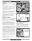
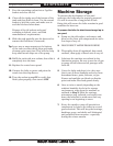
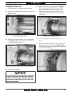
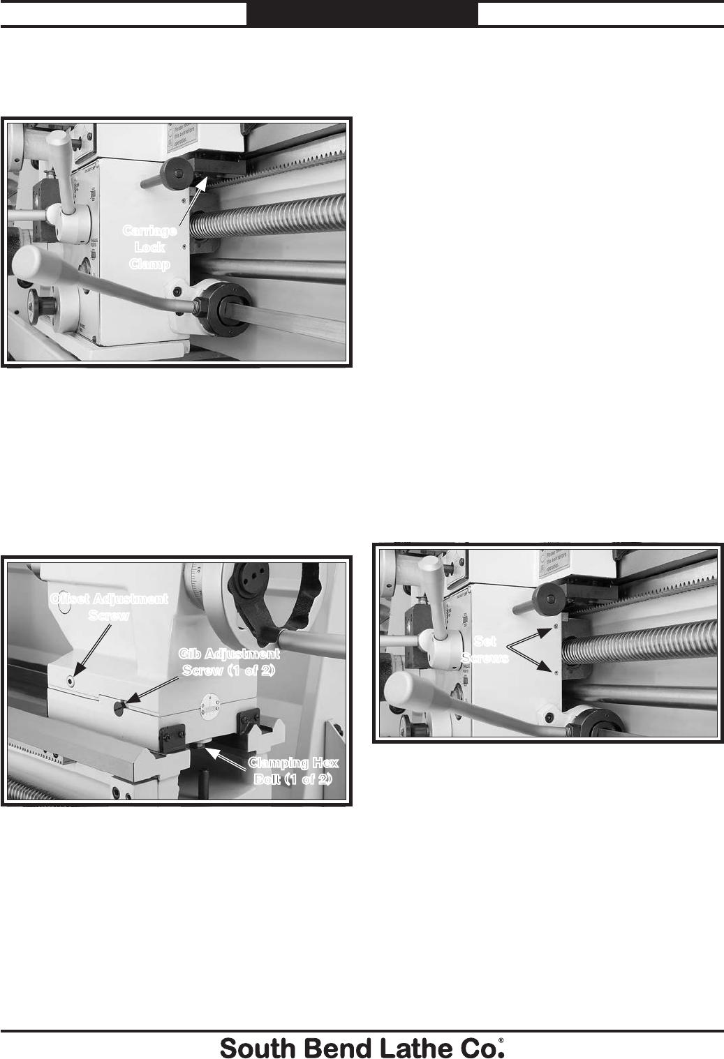
Note: Remove the carriage lock clamp to access
the saddle gib adjustment screw on the tailstock
side (see Figure 127).
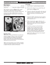
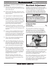
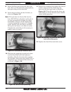
Note: Before adjusting the tailstock gib,
loosen the hex bolts underneath both ends of
the tailstock (see Figure 128) to release the
clamping pressure between the upper and lower
castings. Test the gib adjustment by using the
offset adjustment screws. When you are satisfied
with the setting, retighten the clamping hex
bolts.
Figure 128. Tailstock gib adjustment controls.
Gib Adjustment
Screw (1 of 2)
Clamping Hex
Bolt (1 of 2)
Offset Adjustment
Screw
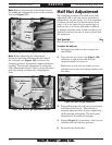
Half Nut Adjustment
The clamping pressure of the half nut is fully
adjustable with a gib that can be loosened or
tightened by two set screws. Use this procedure
to adjust the half nut if it becomes loose from
wear, or it is too tight for your preferences. A
half nut that is too loose will make it difficult
to produce accurate work. A half nut that is too
tight will increase the rate of wear on itself and
the leadscrew.
Tool Needed: Qty
Hex Wrench 3mm .................................................1
To adjust the half nut:
1. Disengage the half nut, then remove the
thread dial.
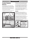
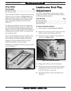
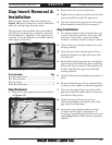
2. Turn the two set screws (see Figure 129)
clockwise to tighten the half nut and
counterclockwise to loosen it.
Make sure to turn the set screws in even
amounts so one does not become tighter than
the other.
3. Engage/disengage the half nut several times
and notice how it feels. The half nut is
correctly adjusted when it has a slight drag
while opening and closing. The movement
should not be too stiff or too sloppy.
4. Repeat Steps 2–3, if necessary, until you are
satisfied with the half nut pressure.
5. Re-install the thread dial.
Figure 129. Half nut gib adjustment.
Set
Screws
Figure 127. Carriage lock clamp.
Carriage
Lock
Clamp