


-52-
For Machines Mfg. Since 3/11
16-Speed Gearhead Lathe
OPERATION
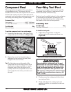
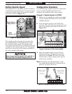
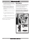
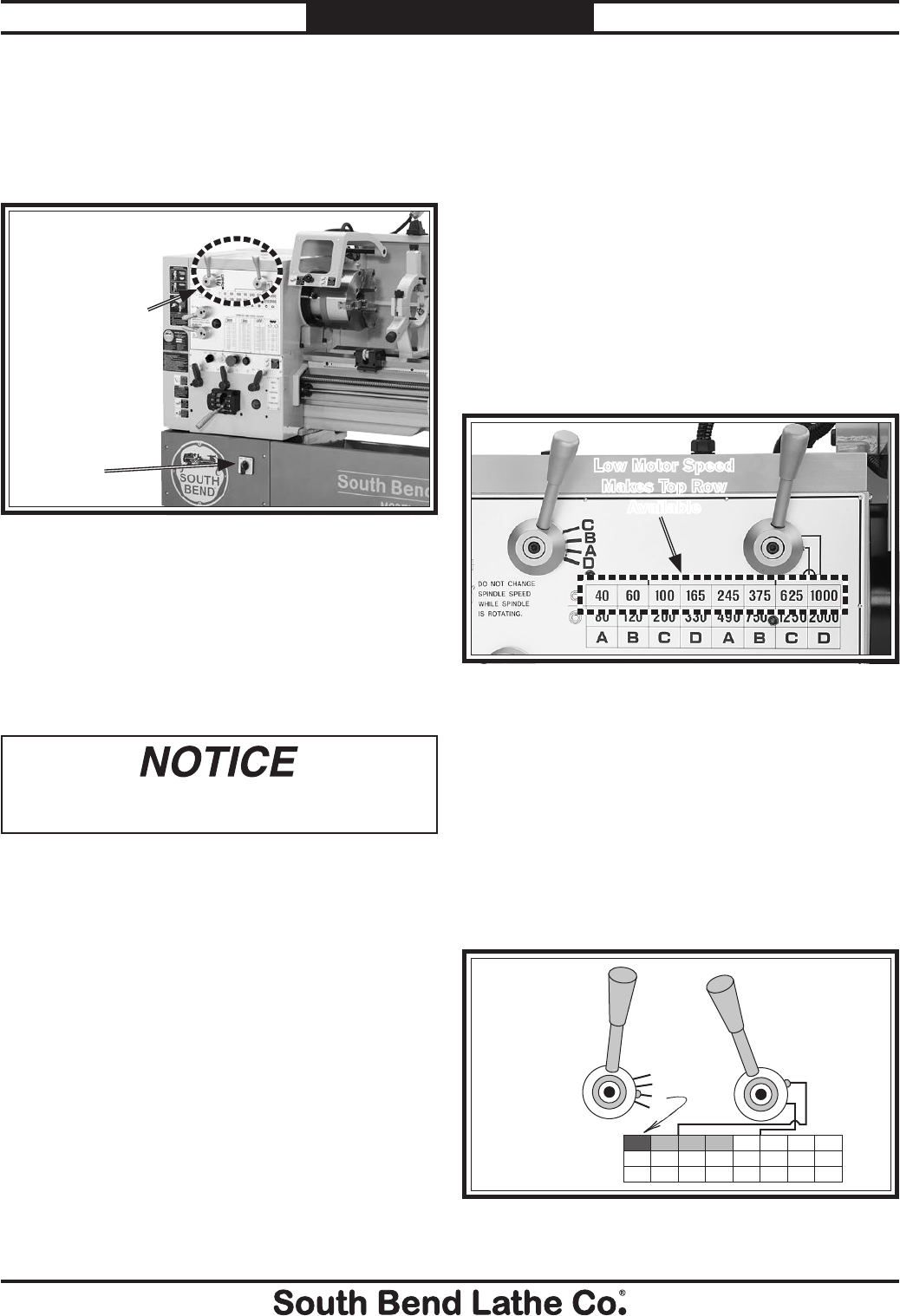
Setting Spindle Speed
Selecting one of the 16 spindle speeds available is
a combination of configuring the two-speed motor
switch, the spindle range lever, and the spindle
speed lever shown in Figure 73.
The spindle speed and range levers control the
gear configuration in the headstock to produce
the selected spindle speed. The spindle range
lever selects speeds in the low or high range to be
available for the spindle speed lever. The spindle
speed lever selects one of the speeds available in
the active spindle speed range.
Never change spindle speeds while spindle is
moving! Severe machine damage will occur.
Figure 73. Spindle speed controls.
Motor
Switch
Spindle Speed
& Range Levers
Configuration Examples
Use the following examples to better understand
how to read the spindle speed chart and
configure the controls for the correct speed.
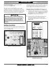
Example 1: Spindle Speed of 40 RPM
1. Make sure the spindle is completely stopped
and the spindle ON/OFF lever is in the OFF
(middle) position.
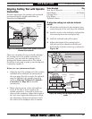
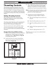
2. Turn the motor switch to the LOW (left)
position. This will make the speeds in the top
row of the spindle speed chart available (see
Figure 74).
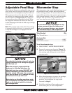
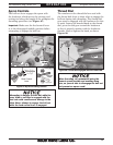
3. Move the spindle range lever so that the
indicator points to the upper line (see the
illustration in Figure 75). This will make
the first four or lower speeds in the top row
of the chart available.
Note: If necessary, use the chuck key to rock
the spindle back-and-forth to help mesh the
gears as you move the levers.
C
B
A
D
Spindle Speed
Lever at “A”
(40 RPM)
Spindle Range
Lever at the
Low Range
10006253752451651006040
2000125075049033020012080
DCBADCBA
Figure 75. Setting the spindle speed at 40 RPM.
Figure 74. A low motor speed makes the spindle
speeds in the top row of the chart available.
Low Motor Speed
Makes Top Row
Available