Performance Tests
1–86
TDS 500D, TDS 600B & TDS 700D Performance Verification and Specifications
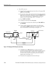
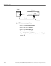
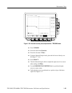
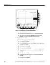
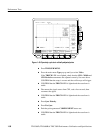
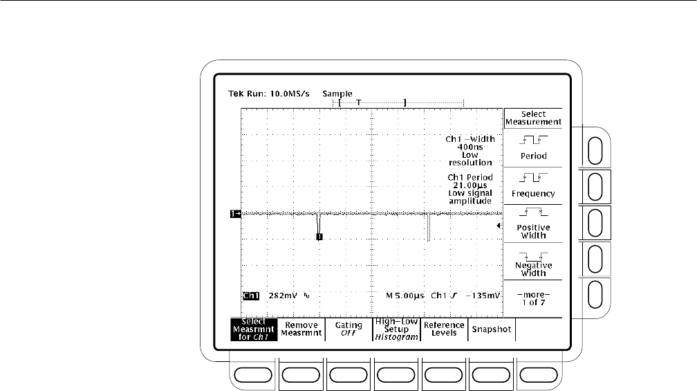
Figure 1–40: Sync duty cycle test: critically adjusted pulse
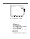
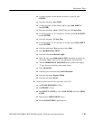
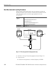
H Press TRIGGER MENU.
H Press the main-menu Type pop-up until you select Video.
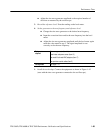
If the TRIG’D LED is not lighted, check that the CH1 – Width and
CH1 Period measurements are adjusted correctly. See note above.
CONFIRM that the setup is correct and the oscilloscope will trigger.
H CONFIRM that the TRIG’D LED is lighted and the waveform is
stable.
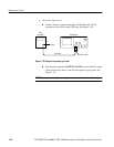
H Disconnect the signal source from CH1, wait a few seconds, then
reconnect the signal.
H CONFIRM that the TRIG’D LED is lighted and the waveform is
stable.
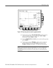
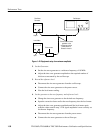
H Press Sync Polarity.
H Press Pos Sync.
H Push the pulse generator COMPLEMENT button out.
H CONFIRM that the TRIG’D LED is lighted and the waveform is
stable.


