Brief Procedures
1–8
TDS 500D, TDS 600B & TDS 700D Performance Verification and Specifications
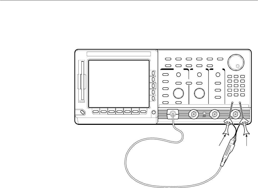
connect the probe ground (typically black) to PROBE COMPENSA-
TION GND. If using a P6243 or P6245 probe, you may want to attach a
Y-lead connector and two SMD KlipChips as shown in Figure 1–3.
Signal Gnd
Figure 1–3: Universal test hookup for functional tests – TDS 600B shown
b. Initialize the oscilloscope:
H Press save/recall SETUP.
H Press the main-menu button Recall Factory Setup.
H Press the side-menu button OK Confirm Factory Init.
2. Verify that all channels operate: Do the following substeps — test CH 1
first, skipping substep a and b since CH 1 is already set up for verification
and as the trigger source from step 1.
a. Select an unverified channel:
H Press WAVEFORM OFF to remove the channel just verified from
display.
H Press the front-panel button that corresponds to the channel you are
to verify.
