Performance Tests
TDS 500D, TDS 600B & TDS 700D Performance Verification and Specifications
1–17
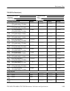
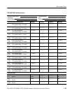
Table 1–1: Test equipment (cont.)
Item number and
description
PurposeExampleMinimum requirements
15. Meter, Level and Power
Sensor
Frequency range:10 MHz to 400 MHz.
Amplitude range: 6 mV
p-p
to 2 V
p-p
Rohde & Schwarz URV 35,
with NRV-Z8 power sensor
1,4
Checking Analog Bandwidth
and Trigger Sensitivity
16. Splitter, Power Frequency range: DC to 1 GHz.
Tracking: >2.0%
Rohde & Schwarz RVZ
1,4
Checking Analog Bandwidth
17. Adapter (four required) Male N-to-female BNC Tektronix part number
103-0045-00
Checking Analog Bandwidth
18. Adapter Female N-to-male BNC Tektronix part number
103-0058-00
Checking Analog Bandwidth
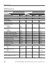
19. Generator, Video Signal Provides PAL compatible outputs Tektronix TSG 121 Used to Test Video Option 05
Equipped Instruments Only
20. Oscillator, Leveled Sine
wave Generator
60 Hz Sine wave Tegam/Tektronix SG 502 (if
available)
1,2
Used to Test Video Option 05
Equipped Instruments Only
21. Pulse Generator Tektronix CFG280
(or Tegam/Tektronix PG 502)
2
Used to Test Video Option 05
Equipped Instruments Only
22. Cable, Coaxial
(two required)
75 W , 36 in, male to male BNC
connectors
Tektronix part number
012-1338-00
Used to Test Video Option 05
Equipped Instruments Only
23. Terminator, 75 W
(two required)
Impedance 75 W; connectors: female
BNC input, male BNC output
Tektronix part number
011-0102-01
Used to Test Video Option 05
Equipped Instruments Only
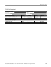
24. Generator, Optical Im-
pulse
850 nm optical impulse Tektronix OIG501 Optical
Impulse Generator
2
Checking Option 3C
25. Generator, Optical Im-
pulse
1300 nm optical impulse Tektronix OIG502 Optical
Impulse Generator
2
Checking Option 4C
26. Attenuator, Optical 62.5 micron optical attenuator Tektronix OA5022 Optical
Attenuator
2
Checking Option 3C and 4C
27. Cable, Fiber Optic FC-FC fiber cable Tektronix part number
174-2322-00
Checking Option 3C and 4C
28. Optical-to-Electrical
Converter
P6701B (used with Option 3C) or
P6703B (used with Option 4C)
optical-to-electrical converter
Tektronix part number
P6701B or P6703B
Checking Option 3C and 4C
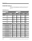
1
You can replace items 9, 10, 11, 14, 15, 16, and 20 with a Wavetek 9100 (with options 100 and 600) for 500 MHz oscillo-
scopes, or a Wavetek 9500 (with option 100) and output head appropriate for the bandwidth of the oscilloscope(s) being
tested.
2
Requires a TM 500 or TM 5000 Series Power Module Mainframe.
3
Warning: The P6243 and P6245 probes that may be used with this oscilloscope provide an extremely low loading
capacitance (<1 pF) to ensure the best possible signal reproduction. These probes should not be used to measure
signals exceeding ±8 V, or errors in signal measurement will be observed. Above 40 V, damage to the probe may result.
To make measurements beyond ±8 V, use either the P6139A probe (good to 500 V), or refer to the catalog for a recom-
mended probe.
4
If available, you can replace items 14, 15, and 16 with the following set of equipment for bandwidths up to 1 GHz:
a Tegam/Tektronix SG503 and SG504 with SG504 leveling head.


