


THS710A, THS720A, THS730A & THS720P Service Manual
3–1
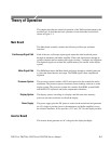
Theory of Operation
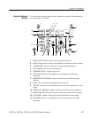
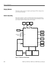
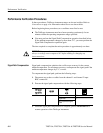
This chapter describes the electrical operation of the TekScope instrument to the
module level. It describes the basic operation of each functional circuit block
shown in Figure 3–1.
Main Board
The Main board assembly contains the following oscilloscope and meter
functions.
Each of the two oscilloscope input signals enters the main board and passes
through an attenuator and buffer amplifier. Then each signal passes through an
isolation interface before reaching the trigger circuitry, a sampler, and a digitizer.
The digitized signals are written into system memory for transfer to the display
system.
The DMM input enters the Main board and passes through a switching network
to select the meter function and range. The DMM signal is then sampled and
digitized.
The processor system contains a 68331 microprocessor that controls the entire
instrument. The processor passes waveforms, meter readings, and text on to the
display system. The processor system also contains flash ROM, system RAM,
and the RS-232, keyboard, and probe compensation interfaces.
The display system, consisting of a display controller and video memory,
processes text and waveforms to refresh the display.
The power supply provides DC power to ciruits on the main board and generates
an AC voltage to provide power to the attenuators and buffer amplifiers across
the isolation interfaces. It also provides +12 V and –20 V for the display module.
Inverter Board
The inverter board generates an AC voltage for the display backlight.
Oscilloscope Signal Path
Meter Signal Path
Processor System
Display System
Power Supply