


Performance Verification
THS710A, THS720A, THS730A & THS720P Service Manual
4–7
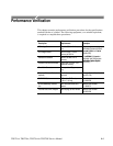
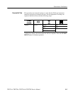
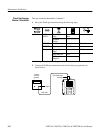
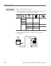
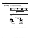
4. For each VOLTS/DIV setting listed below, perform the following steps:
a. Set the DC voltage source output level to the positive voltage listed and
then record the mean measurement as V
pos
.
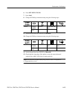
b. Reverse the polarity of the DC voltage source and then record the mean
measurement as V
neg
.
c. Calculate V
diff
= V
pos
– V
neg
and then compare V
diff
to the accuracy
limits in the table.
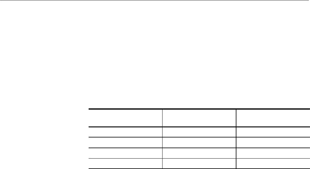
VOLTS/DIV Setting
DC Voltage Source Output
Levels
Accuracy Limits for V
diff
5 mV/div +17.5 mV, –17.5 mV 34.05 mV to 35.95 mV
500 mV/div +1.75 V, –1.75 V 3.405 V to 3.595 V
2 V/div +7.00 V, –7.00 V 13.62 V to 14.38 V
10 V/div +35.0 V, –35.0 V 68.1 V to 71.9 V
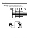
5. Set DC voltage source output level to 0 V.
6. To check channel 2, repeat step 2 substituting CH 2 for CH 1.
7. Press CH 1 and WAVEFORM OFF to remove the channel 1 waveform
from the display.
8. Repeat steps 3 through 5, substituting CH 2 for CH 1, to complete the check
of channel 2.