


Adjustment Procedures
5–4
THS710A, THS720A, THS730A & THS720P Service Manual
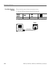
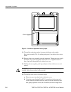
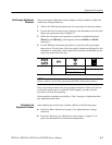
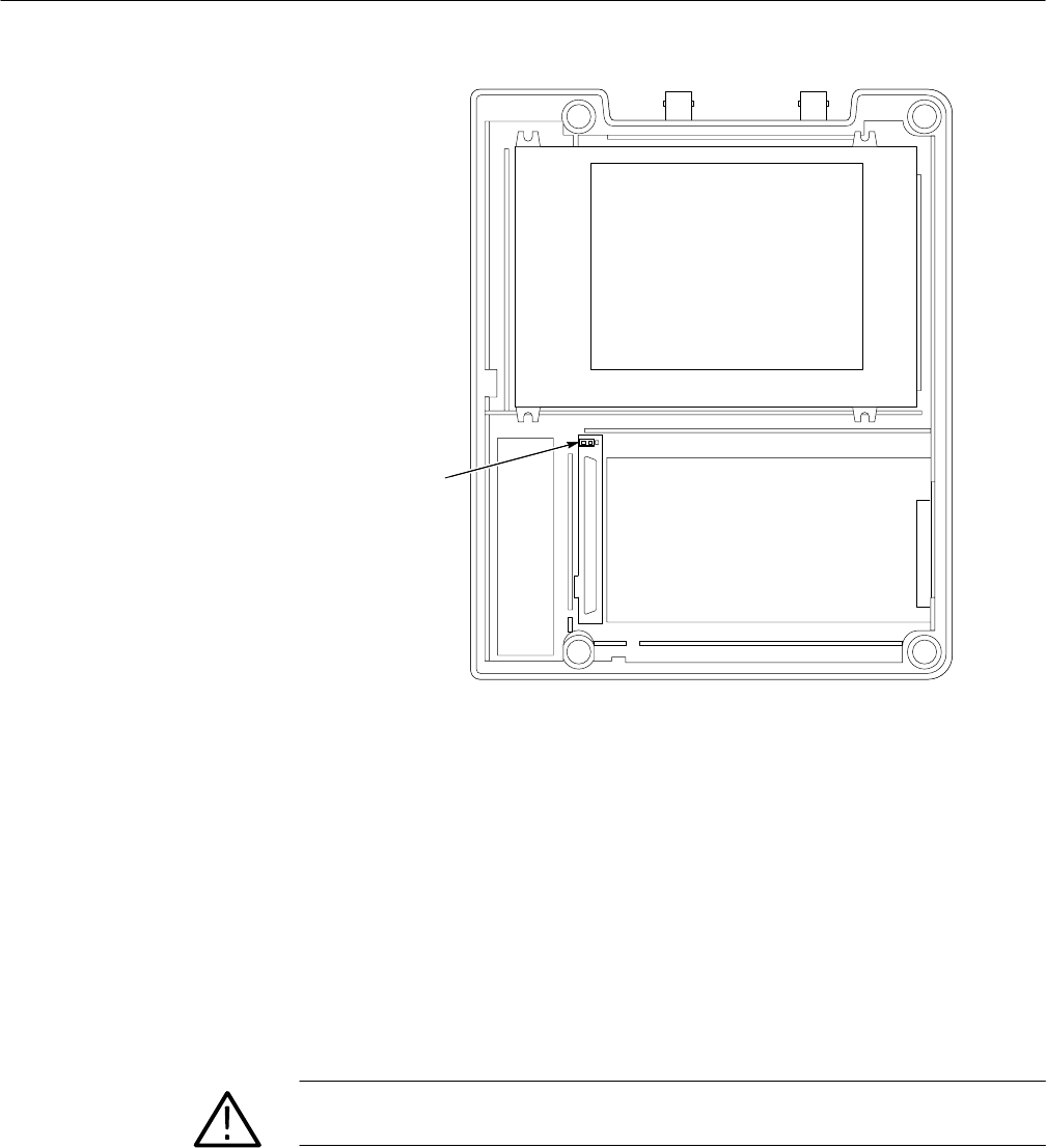
Adjustment-lockout
jumper
Figure 5–1: Location of adjustment-lockout jumper
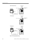
11. To install the switch mat, place it (contact side down) on the switch
flex-circuit assembly. The five rubber guideposts fit into holes in the circuit
board.
12. Place the front cover assembly onto the instrument. Taking care not to pinch
the handle, align it into the guides in the front cover. Align the buttons so
they all protrude through the holes in the front cover.
13. Holding the case together, pick it up and place it front side down on a soft
surface.
CAUTION. To avoid cross-threading or cutting new threads with the screws,
carefully follow the procedure in the next step.
14. To install the four screws, follow these steps:
a. Place the screws into their holes in the back cover.
b. Using the torque-limiting Torx T-15 screwdriver, slowly turn each
screw backward (counterclockwise) until you feel the thread drop and
then gently tighten the screw (turn clockwise) into the existing thread.