


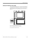


Maintenance
6–6
THS710A, THS720A, THS730A & THS720P Service Manual
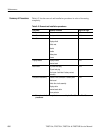
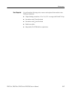
Table 6–2 lists the removal and installation procedures in order of increasing
complexity.
Table 6–2: Removal and installation procedures
Procedure Modules Accessed Begins on Page
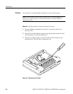
Tilt Stand Tilt stand 6–8
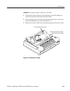
Front-Panel Label Front-panel label 6–10
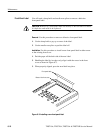
Front Cover Front cover
Display shield
Switch mat
Gasket
Handle
Battery door
Screws
6–11
Display Module Display module
Inverter board
6–16
Back Cover DC power hole plug
I/O port hole plug
Back cover / back label / battery contact
assembly
6–19
Complete Disassembly Chassis / BNC connectors / banana jacks
Main board
Switch flex-circuit assembly
Display cable
Inverter board cable
Foam pad set
2
6–23
2
Some pieces in the foam pad set are accessed by the Front Cover and Back Cover
procedures.
Summary of Procedures