


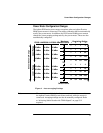

Measuring TDMA Signals
25
Measuring TDMA Signals
Power Meter and Sensor Operation
The voltages generated by the diode detectors in the power sensor can be very
small. Gain and signal conditioning are required to allow accurate
measurement. This is achieved using a 220 Hz (440 Hz in fast mode) square
wave output from the power meter to drive a chopper-amplifier in the power
sensor. Digital Signal Processing (DSP) of the generated square wave is used
by the power meter to recover the power sensor output and accurately
calculate the power level.
The chopper-amplifier technique provides noise immunity and allows large
physical distances between power sensor and power meter (Agilent 11730
series cables available up to 61 metres). Additional averaging helps reduce
noise susceptibility.
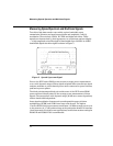
Achieving Stable Results with TDMA Signals
The averaging settings in the power meter are designed to reduce noise when
measuring continuous wave (CW) signals. Initial measurement of a pulsed
signal may appear unstable with jitter on the less significant displayed digits.
With pulsed signals the averaging period must be increased to allow
measurement over many cycles of the pulsed signal.
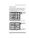
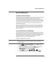
To set the averaging proceed as follows:
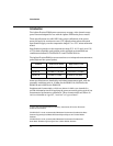
Note The example shows the key labels for a single channel power meter.
Dual channel meter are similar, adding only channel identification to
the softkey labels.
1. Press , , . Press the softkey to
access the filter menu.
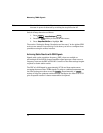
2. The filter setting is displayed under the softkey label. To
change this setting first set manual mode by pressing the
softkey to highlight .
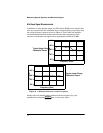
3. Press and use the , , or to set the
averaging you require. Confirm your entry by pressing .
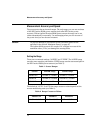
System
Inputs
Input Settings
More
Filter
Length
Mode Man Auto Man
Length
Enter