


Service
67
Service
Service instructions consist of principles of operation, troubleshooting, and
repairs.
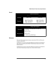
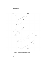
Principles of Operation
The A1 Bulkhead assembly on the Agilent E-series E9300 power sensors
provides a 50 ohm load to the RF signal applied to the power sensor. The A1
Bulkhead assembly on the E9300/1B sensors includes a 30 dB attenuator that
can be disconnected by means of a Type-N connector. The A1 Bulkhead
assembly on the E9300/1H sensors includes a 10 dB attenuator in the front end.
A dual range GaAs diode pair/attenuator/diode pair assembly in the bulkhead
rectifies the applied RF to produce dc voltages (high and low ranges) which
vary with the RF power across the 50 ohm load. Thus the voltage varies with
the RF power dissipated in the load.
The low-level dc voltages from the bulkhead assembly are amplified before
they are transferred on standard cables to the power meter. The amplification
is provided by an input amplifier assembly which consists of a chopper
(sampling gate) and an input amplifier. The chopper circuit converts the dc
voltages to ac voltages. The chopper is controlled by a 220 Hz square wave
generated by the power meter. The amplitude of the sampling gate output is a
220 Hz square wave which varies with the RF power input. The 220 Hz ac
output is applied to an amplifier which provides the input to the power meter.
The Agilent EPM series power meter automatically detects when an
Agilent E-series E9300 power sensor is connected and downloads the
correction data from the sensor’s EEPROM. In the E9300/1B/H the EEPROM
contains an offset value for the measured attenuation value of the attenuator
used in the bulkhead assembly. Thus, the attenuator is matched to a particular
sensor. The auto-averaging settings are also configured automatically for use
with Agilent E-series E9300 power sensors. This configures the power meter to
operate over the range with that particular sensor’s unique correction data
applied.