


Measurement Accuracy and Speed
29
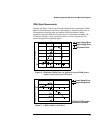
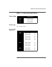
Configure the power meter as follows:
Note The example shows the key labels for a single channel power meter.
Dual channel meters are similar, adding channel identification to the
softkey labels.
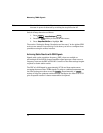
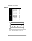
1. Press , . The current setting is displayed under
the softkey.
2. To change this press . A pop up window appears. Use or
to highlight your choice.
To confirm your choice press .
The section “Setting the Range, Resolution and Accuracy” in the Agilent EPM
series power meters Programming Guide shows you how to configure these
parameters using the remote interface
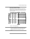
Measurement Considerations
While autoranging is a good starting point, it is not ideal for all measurements.
Signal conditions such as crest factor or duty cycle may cause the power meter
to select a range which is not the optimum configuration for your specific
measurement needs. Signals with average power levels close to the range
switch point require you to consider your needs for measurement accuracy
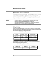
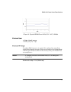
and speed. For example, using an Agilent E9300/1/4A sensor, where the range
switch point is -10 ± 0.5 dBm in a pulsed signal configured as follows:
the calculated average power is -12 dBm.
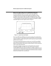
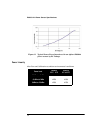
Accuracy
The value of -12 dBm lies in the lower range of the Agilent E-series E9300
power sensor. In autoranging mode (“AUTO”) the Agilent EPM series power
meter determines the average power level is below -10 dBm and selects the
low power path. However, the peak amplitude of -6 dBm is beyond the
specified, square law response range of the low power path diodes.The high
Characteristic Value
Peak Amplitude -6 dBm
Duty Cycle 25 %
System
Inputs
Input Settings
Range
Range
Enter