


-19-
$"
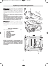
To prevent personal injury, always
dis con nect plug from power source
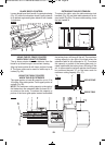
before making any adjustments. The rip fence must
be parallel with the SAWBLADE in order to prevent
KICKBACK when ripping.
Your table saw is equipped with a Self-Aligning,
Squarelock™ rip fence. Once the adjustments
below have been made, the rip fence will self align
when the fence is locked into position.
!&The blade must be parallel with the miter
gauge slots (see page 18) and be perpendicular to
table before proceeding with rip fence alignment.
To prevent personal injury, always
make sure the rip fence is locked
before making rip cuts.
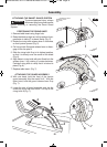
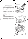
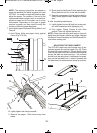
1. Lift both guard barriers to their up locked posi-
tion.
2. Raise lock handle and slide fence until it is
alongside the sawblade, by lifting right side pawl
above fence (Fig. 23).
The fence should touch the blade teeth at the
front and rear of the blade. If fence does not touch
the teeth at front and rear of blade continue with
the following the steps:
3. Loosen the two screws on the top front section
of the rip fence using the included 5mm hex
wrench.
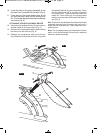
4. Move fence until it touches the teeth and is
parallel to the blade.
5. Hold fence in place and lower lock handle, check
to make sure the fence stayed parallel to the
blade then tighten screws (Fig. 23).
6. Clamp rip fence to check if it holds securely at
front and rear. If rear is not clamped securely, un-
clamp fence and turn rear clamp adjustment
screw clockwise for increased clamp ing. Try
clamping the fence to verify if it self aligns and
clamps tightly at the front and rear. Overtightening
of the rear clamp adjustment screw will cause
the rip fence to be non-self aligning (Fig. 23).
Overtightening may cause friction or “chatter”
when fence is moved side to side.
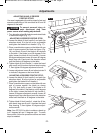
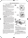
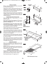
$" "! &$'%& &
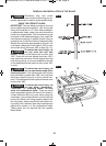
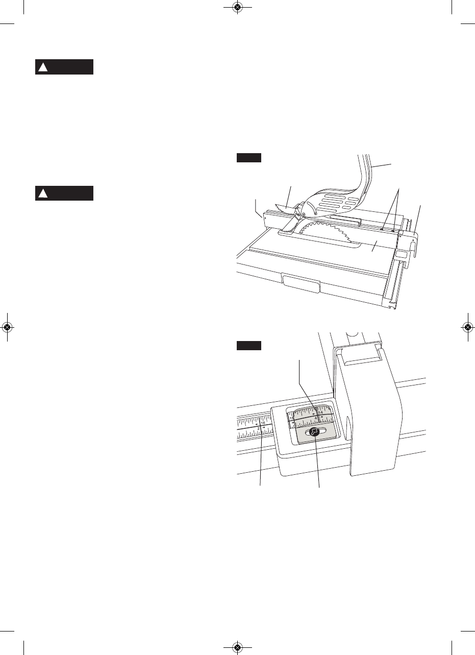
The distance of the rip fence body from the blade
when ripping on the right side of the blade is deter-
mined by lining the pointer with the desired dimen-
sion on the scale (Fig. 24).
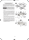
&!%&&$" "! &$
1. Lift both guard barriers to their up locked posi-
tion (Fig. 23).
2. Raise lock handle and slide fence until it is
alongside the sawblade, by lifting right side pawl
above fence. Lock fence in place (Fig. 23).
3. Loosen pointer adjustment screw , adjust pointer
to “0” mark on lower scale , then re-tighten
screw (Fig. 24).
3
2
5
6
4
FIG. 23
1
7
8
9
FIG. 24
!
WARNING
!
WARNING
BM 2610014415 01-11 E:BM 2610012089 12-10 E 1/10/11 7:17 AM Page 19