


-6-
;A.81:?A8-@10&;;8?
Double insulation is a design concept used in
electric power tools which eliminates the need for
the three wire grounded power cord and grounded
power supply system. It is a recognized and ap-
proved system by Underwriter’s Laboratories, CSA
and Federal OSHA authorities.
"!$& & Servicing of a tool with double insu-
lation requires care and knowledge of the system
and should be performed only by a qualified service
technician.
WHEN SERVICING, USE ONLY IDENTICAL RE-
PLACEMENT PARTS.
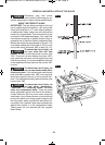
POLARIZED PLUGS. To reduce the risk of electri-
cal shock, your tool is equipped with a polarized plug
(one blade is wider than the other), this plug will fit
in a polarized outlet only one way. If the plug does
not fit fully in the outlet, reverse the plug. If it still does
not fit, contact a qualified electrician to install the
proper outlet. To reduce the risk of electrical shock,
do not change the plug in any way.
*& %! !$%
Replace damaged cords immedi-
ately. Use of damaged cords can
shock, burn or electrocute.
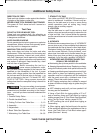
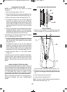
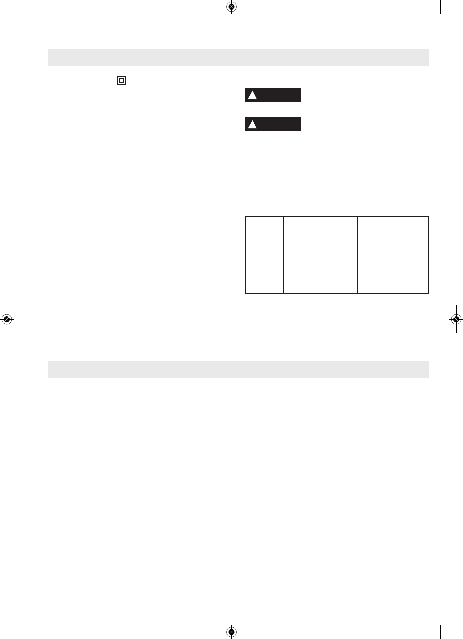
If an extension cord is necessary, a
cord with adequate size conductors
should be used to prevent excessive voltage drop,
loss of power or overheating. The table shows the
correct size to use, depending on cord length and
nameplate amperage rating of tool. If in doubt, use
the next heavier gauge. Always use U.L. and CSA
listed extension cords.
$! %,%!*& %! !$%
(!&&$ & '$$ &&!!%
NOTE: The smaller the gauge number, the heavier
the cord.
&;;8K?
9<1>1
$-@5:3
;>0%5F15:)
)5>1%5F1?5:99
3-6
6-8
8-10
10-12
12-16
18 16 16 14 0.75 0.75 1.5 2.5
18 16 14 12 0.75 1.0 2.5 4.0
18 16 14 12 0.75 1.0 2.5 4.0
16 16 14 12 1.0 2.5 4.0 —
14 12 — — — — — —
25 50 100 150 15 30 60 120
;>01:3@45:11@ ;>01:3@45:1@1>?
&-.81;2;:@1:@?
Page
General Safety Rules . . . . . . . . . . . . . . . . . . . . .2
Additional Safety Rules . . . . . . . . . . . . . . . . .3–5
Double Insulated Tools & Extension Cords . . . .6
Table of Contents . . . . . . . . . . . . . . . . . . . . . .6-7
Glossary of Terms . . . . . . . . . . . . . . . . . . . . . .7-8
Tools Needed For Assembly . . . . . . . . . . . . . . .8
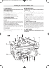
Getting To Know Your Table Saw . . . . . . . . .9, 10
Power Switch . . . . . . . . . . . . . . . . . . . . . . . . .9
Elevation Wheel . . . . . . . . . . . . . . . . . . . . . .9
Blade Bevel Lock Handle . . . . . . . . . . . . . . .9
Blade Bevel Scale . . . . . . . . . . . . . . . . . . . . .9
Base . . . . . . . . . . . . . . . . . . . . . . . . . . . . . . .9
Table Extension Lock Handle . . . . . . . . . . . .9
Push Stick . . . . . . . . . . . . . . . . . . . . . . . . . . .9
Table Extension . . . . . . . . . . . . . . . . . . . . . . .9
Rip Fence . . . . . . . . . . . . . . . . . . . . . . . . . . .9
Rip Fence Scale . . . . . . . . . . . . . . . . . . . . . .9
Smart Guard System . . . . . . . . . . . . . . . . . .9
Page
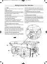
Table Insert . . . . . . . . . . . . . . . . . . . . . . . . . .9
Table . . . . . . . . . . . . . . . . . . . . . . . . . . . . . .10
Miter Gauge . . . . . . . . . . . . . . . . . . . . . . . . .10
Cord Wrap . . . . . . . . . . . . . . . . . . . . . . . . . .10
Rip Fence Storage . . . . . . . . . . . . . . . . . . .10
Push Stick & Wrench Storage . . . . . . . . . .10
One-Handed Carry Handle . . . . . . . . . . . . .10
Smart Guard System Storage . . . . . . . . . .10
Dust Port/Vacuum Hook-Up . . . . . . . . . . . .10
Anti-Kickback Device Storage . . . . . . . . . .10
Miter Gauge Storage . . . . . . . . . . . . . . . . . .10
Hex Wrench & Storage compartment . . . .10
Stand Attachment Bracket . . . . . . . . . . . . .10
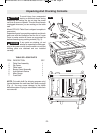
Unpacking and Checking Contents . . . . . . . . .11
Table of Loose Parts . . . . . . . . . . . . . . . . . .11
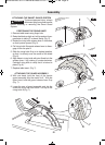
Assembly . . . . . . . . . . . . . . . . . . . . . . . . . .12–16
Attaching Smart Guard
System Components . . . . . . . . . . . . . .12, 13
H%(&% %&$'&! %I
!
WARNING
!
WARNING
BM 2610014415 01-11 E:BM 2610012089 12-10 E 1/10/11 7:17 AM Page 6