


Managing the Hub at the Module Level 2-29
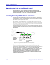
Using the TRMMIM Hub View
FNB Bypass States
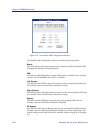
Figure 2-14 shows that all three modules are inserted into FNB 1, as opposed to
being bypassed from the FNB by a multiplexer. There are two possible status
conditions for a Token Ring module:
INS
The Bypass multiplexer is disabled, and all station ports and ring ports can be
connected to the FNB (depending on the status of the surrounding boards and
FNB connections).
BYP
The module is Bypassed, and the MIM ports form a self-contained ring. Stations
connected to the ports can communicate with each other, but they can’t pass
frames to the main ring. Ring ports are unaffected by the Bypass state (unless you
are modeling an older TRMIM-10R or TRMIM-20R; with these two modules, all
ports on the board enter bypass state and are isolated from the main ring). They
can communicate with other Token Ring modules if the FNB connection status
allows, but station ports on the MIM are no longer connected to the ring ports.
Ring ports can be separately bypassed using the RP Bypass option in the Module
FNB Configuration window. See Using the Module FNB Configuration Window
for details.
Manipulating the FNB in the Hub View
To change a module’s FNB left and right connections from within the Hub View:
1. Click mouse button 1 on the appropriate FNB connection symbol to toggle
between disabled and enabled.
To change a module’s FNB Bypass state from within the Hub View:
1. Click mouse button 1 on the Bypass State box at the top of the module to
toggle between BYP and INS.
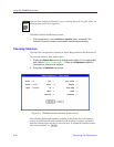
Using the Module FNB Configuration Window
The Module FNB Configuration window allows you to manipulate a module’s
FNB left and right connections and FNB Bypass state. You can also bypass a
module’s ring ports using this window. The window lists each FNB interface
available for a module (for the TRMMIM, only FNB 1 is available), allowing you
to select the FNB and quickly apply the desired settings. To open the Module FNB
Configuration window:
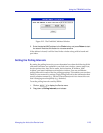
1. Click mouse button 3 on the Module Name, FNB State, or Port Display
Form box to display the Module menu.
2. Drag down to FNB Status, and release. The Module FNB Configuration
window, Figure 2-15, will appear.