


2-12
Cisco 7600 Series Router Supervisor Engine and Route Switch Processor Guide
OL-10100-04
Chapter 2 Route Switch Processors and Supervisor Engines
Supervisor Engine 720 and Supervisor Engine 32
Supervisor Engine 720 and Supervisor Engine 32
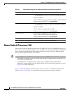
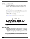
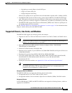
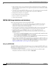
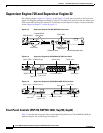
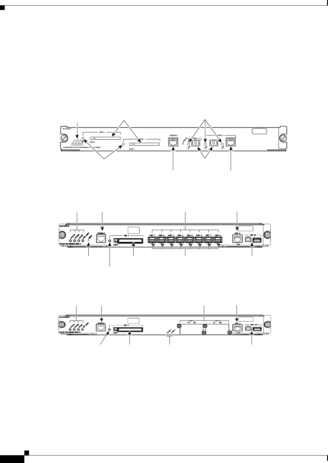
The following figures (Figure 2-3, Figure 2-4, and Figure 2-5) show the front panel on the Supervisor
Engine 720 (Sup720) and Supervisor Engine 32 (Sup32). The tables that follow describe the controls and
LEDs on the RSP720, Sup720, and Sup32. For information on the Supervisor Engine 2 controls and LEDs,
see the
“Supervisor Engine 2” section on page 2-14.
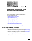
Figure 2-3 Supervisor Engine 720 (WS-SUP720) Front Panel
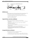
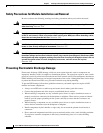
Figure 2-4 Supervisor Engine 32 (WS-SUP32-GE-3B) Front Panel
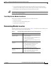
Figure 2-5 Supervisor Engine 32 (WS-SUP32-10GE-3B) Front Panel
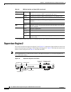
Front-Panel Controls (RSP720, RSP720-10GE, Sup720, Sup32)
Table 2-2 describes the front-panel controls on the Route Switch Processor 720 and RSP720-10GE, the
Supervisor Engine 720, and the Supervisor Engine 32.
87890
STATUS LEDs
Disk LEDs
CONSOLE port
LINK LEDs
Gigabit Ethernet
uplink port
10/100/1000 uplink port
CompactFlash
Type II slots
120690
CONSOLE port
CompactFlash
Type II slot
Status LEDs
RESET button
Uplink ports
USB ports
Link Status LEDs
Disk LED
Uplink port
120691
CONSOLE port
CompactFlash
Type II slot
Status LEDs
Uplink ports
USB ports
Link Status LEDs
Disk LED
Uplink port