


3-7
Cisco 7600 Series Router Supervisor Engine and Route Switch Processor Guide
OL-10100-04
Chapter 3 Installing and Configuring Route Switch Processors and Supervisor Engines
Removing a Supervisor Engine or Route Switch Processor
Removing a Supervisor Engine or Route Switch Processor
Before you remove a supervisor engine or route switch processor (RSP) from the router, you should first
save the current configuration using the write {host file | network | terminal} command. This step saves
time when bringing the module back online. You can recover the configuration by downloading it from
the server to the nonvolatile memory of the supervisor engine or RSP.
If the module is running Cisco IOS software, save the current running configuration by entering the
copy
running-config startup-config command.
Warning
Hazardous voltage or energy is present on the backplane when the system is operating. Use caution
when servicing.
Statement 1034
Warning
Invisible laser radiation may be emitted from disconnected fibers or connectors. Do not stare into
beams or view directly with optical instruments.
Statement 1051
To remove a supervisor engine or RSP, perform these steps:
Step 1 Disconnect any cables attached to ports on the module.
Step 2 Verify that the captive installation screws on all of the modules in the chassis are tight. This step assures
that the space created by the removed module is maintained.
Note If the captive installation screws are loose, the EMI gaskets on the installed modules will push
the modules toward the open slot, which reduces the opening size and makes it difficult to
remove the module.
Step 3 Loosen the two captive installation screws on the module you plan to remove from the chassis.
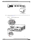
Step 4 Place your thumbs on the ejector levers (see Figure 3-1) and simultaneously rotate the ejector levers
outward to unseat the module from the backplane connector.
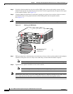
Step 5 Grasp the front edge of the module and slide the module straight out of the slot. If the chassis has
horizontal slots, place your hand under the module to support its weight as you slide it out from the slot.
Do not touch the module circuitry.
Caution To prevent ESD damage, handle modules by the carrier edges only.
Step 6 Place the module on an antistatic mat or antistatic foam, or immediately reinstall the module in another slot.
Step 7 Install blank module filler plates (Cisco part number 800-00292-01) in any empty slots to keep dust out
of the chassis and to maintain consistent airflow through the chassis.
Warning
Blank faceplates and cover panels serve three important functions: they prevent exposure to
hazardous voltages and currents inside the chassis; they contain electromagnetic interference (EMI)
that might disrupt other equipment; and they direct the flow of cooling air through the chassis. Do not
operate the system unless all cards, faceplates, front covers, and rear covers are in place.
Statement 1029