


2-13
Cisco 7600 Series Router Supervisor Engine and Route Switch Processor Guide
OL-10100-04
Chapter 2 Route Switch Processors and Supervisor Engines
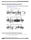
Supervisor Engine 720 and Supervisor Engine 32
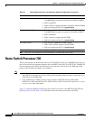
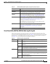
Front-Panel LEDs (RSP720, RSP720-10GE, Sup720, Sup32)
LEDs on the front panel of the supervisor engine or route switch processor show the status of the
processor and other components installed in the router.
Table 2-3 lists the LED functions on the Route
Switch Processor 720 and RSP720-10GE, the Supervisor Engine 720, and the Supervisor Engine 32.
See
Table 2-5 for a list of LED functions on the Supervisor Engine 2.
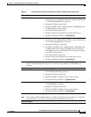
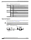
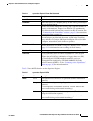
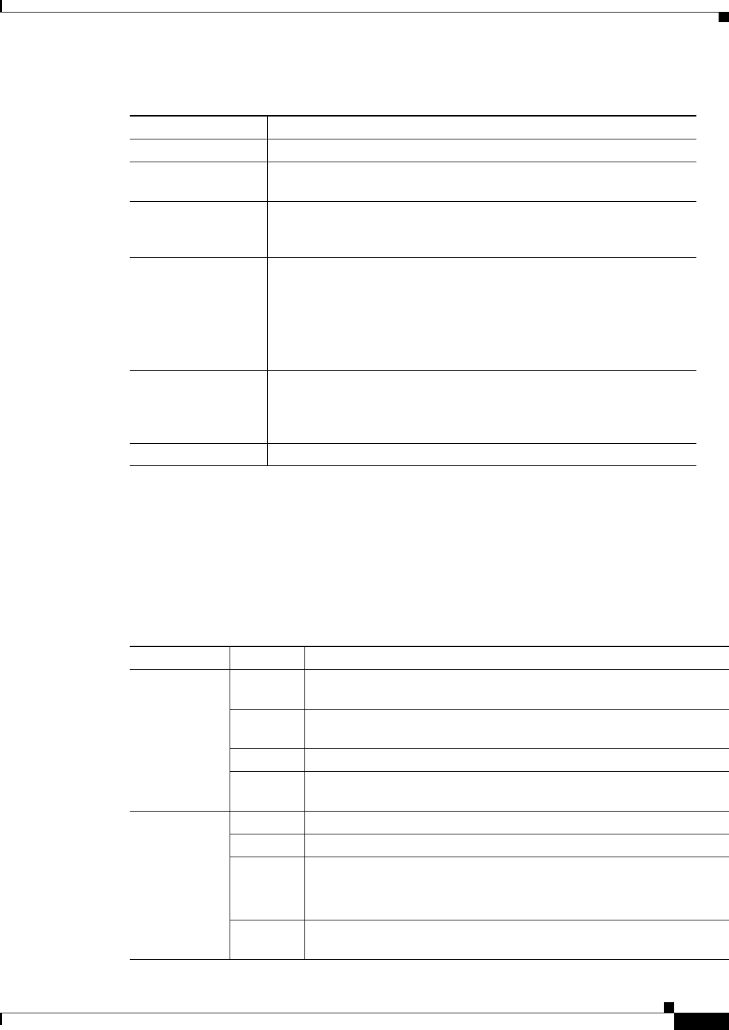
Tab le 2-2 RSP720, RSP720-10GE, Sup720, and Sup32 Front-Panel Controls
Component Description
Status LEDs
Indicate the status of various functions on the module (see Table 2-3).
Reset Button
Restarts the router. Use a ballpoint pen tip or other small, pointed object to
access the Reset button. Not all modules have a Reset button.
CompactFlash
Disk Slots
One or two slots for flash memory cards. Do not remove the card from
the slot while the disk LED is on. See the
“Using Flash Memory Cards”
section on page 3-12 for information about working with flash memory.
Console Port
Provides access to the router. The port is an EIA/TIA-232 asynchronous,
serial connection with hardware flow control and an RJ-45 connector.
See the
“Connecting to the Console Port” section on page 3-9 for
instructions on connecting to the console port.
On the RSP720, the console port allows you to access either the switch
processor (SP) or the route processor (RP).
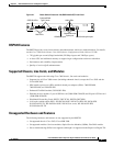
Uplink Ports
Used to connect the router to other network devices. The uplink ports are
configurable with SFP, XENPAK, or X2 optics modules. See the
“Connecting to the Uplink Ports” section on page 3-10 for more
information.
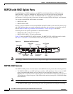
USB Ports (Sup32 only)
Each USB port can function as a console port or security key.
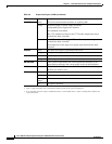
Tab le 2-3 RSP720, Sup720, and Sup32 LEDs
LED Color Description
STATUS
Green All diagnostics pass; the module is operational (normal initialization
sequence).
Orange The module is booting or running diagnostics (normal initialization
sequence).
Yellow Minor hardware problems.
Red An overtemperature condition occurred. (A major threshold has been
exceeded during environmental monitoring.)
SYSTEM
1
Green All chassis environmental monitors are reporting OK.
Orange The module is powering up or a minor hardware fault has occurred.
Red Major hardware problem.
The temperature of the supervisor engine or RSP has exceeded the major
temperature threshold.
Blinking
Red
Continuous backplane stall.