


B-10
Cisco 7600 Series Router Supervisor Engine and Route Switch Processor Guide
OL-10100-04
Appendix B Cable and Connector Specifications
RJ-45 Connector
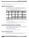
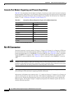
Console Port Mode 2 Signaling and Pinouts (Sup2 Only)
Table B-11 lists the pinouts for the Supervisor Engine 2 console port mode switch in mode 2 (switch in
the out position). In this mode, you can connect a terminal to the supervisor engine using a Catalyst 5000
family Supervisor Engine III console cable and adapter (not provided). For instructions, see “Supervisor
Engine 2” in the
“Connecting a Terminal” section on page 3-9.
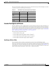
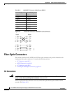
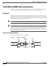
RJ-45 Connector
The RJ-45 connector is used to connect a Category 3, Category 5, Category 5e, or Category 6 FTP from
the external network to the module interface connector. (See
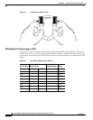
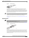
Figure B-2.) Table B-12 lists the connector
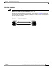
pinouts and signal names for a 10/100BASE-T crossover (MDI-X) cable. Figure B-3 shows a schematic
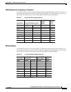
of the 10/100BASE-T crossover cable. Table B-13 lists the connector pinouts and signal names for a
1000BASE-T crossover (MDI-X) cable. Figure B-4 shows a schematic of the 1000BASE-T crossover
cable.
Caution Category 5e and Category 6 cables can store high levels of static electricity because of the dielectric
properties of the materials used in their construction. Always ground the cables (especially in new cable
runs) to a suitable and safe earth ground before connecting them to the module.
Caution To comply with Telcordia GR-1089 intrabuilding, lightning-immunity requirements, you must use
foil-twisted pair (FTP) cable that is properly grounded at both ends.
Inline power for IP phones uses connector pins 1, 2, 3, and 6 in a Category 5, Category 5e, or Category 6
cable to transmit power (6.3
W) from the router. This method of supplying power is sometimes called
phantom power because the IP phone power travels over the same pairs of wires used to transmit the
Ethernet signals. The IP phone voltage is completely transparent to the Ethernet signals and does not
interfere with their operation.
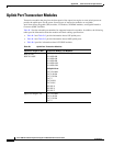
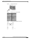
Tab le B-11 Console Port Pinouts (Supervisor Engine 2, Port Mode Switch Out)
Console Port Console Device
Pin (Signal Name) Input/Output
1 (RTS)
1
1. Pin 1 is connected internally to Pin 8.
Output
2 (DTR) Output
3 (RxD) Input
4 (GND) GND
5 (GND) GND
6 (TxD) Output
7 (DSR) Input
8 (CTS)
1
Input