


2-16
Cisco 7600 Series Router Supervisor Engine and Route Switch Processor Guide
OL-10100-04
Chapter 2 Route Switch Processors and Supervisor Engines
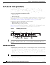
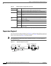
Supervisor Engine 2
SYSTEM
1
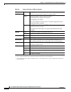
Green All chassis environmental monitors are reporting OK.
Orange The power supply or power supply fan failed.
Incompatible power supplies are installed.
The redundant clock failed.
One VTT
2
module has failed or the VTT module temperature minor
threshold has been exceeded.
3
Red Two VTT modules failed or the VTT module temperature major
threshold has been exceeded.
3
The temperature of the supervisor engine major threshold has been
exceeded.
CONSOLE
Green The supervisor engine is operational and active.
Orange The supervisor engine is in standby mode.
PWR MGMT
1
Green Sufficient power is available for all modules.
Orange Sufficient power is not available for all modules.
SWITCH LOAD
- If the system is operational, the switch load meter indicates (as an
approximate percentage) the current traffic load over the backplane.
PCMCIA
- The PCMCIA LED is lit when no PCMCIA card is in the slot and goes
off when you insert a card.
LINK
Green The port is operational.
Orange The link has been disabled by software.
Flashing
orange
The link is bad and has been disabled due to a hardware failure.
Off No signal is detected.
1. The SYSTEM and PWR MGMT LED indications on a redundant supervisor engine are synchronized to the active engine.
2. VTT = voltage termination. The VTT module terminates signals on the system switching bus.
3. If no redundant supervisor engine is installed and there is a VTT module minor or major overtemperature condition, the
system shuts down.
Table 2-5 Supervisor Engine 2 LEDs (continued)
LED Color Description