


3-3
Cisco 7600 Series Router Supervisor Engine and Route Switch Processor Guide
OL-10100-04
Chapter 3 Installing and Configuring Route Switch Processors and Supervisor Engines
Determining Module Location
• Avoid contact between the printed circuit boards and clothing. The wrist strap only protects
components from ESD voltages on the body; ESD voltages on clothing can still cause damage.
• Never attempt to remove the printed circuit board from the metal carrier.
Caution Periodically check the resistance value of the antistatic strap. The measurement should be within the
range of 1 and 10 megohms (Mohms).
Tools Required for Module Installation
These tools are required to install modules in the Cisco 7600 series router:
• Flat-blade screwdriver
• Antistatic wrist strap or other grounding device
• Antistatic mat or antistatic foam
Determining Module Location
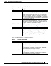
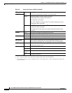
Determine which chassis slot to install the module in. Table 3-1 lists the chassis slots in which you can
install a supervisor engine or route switch processor.
Tab le 3-1 Supervisor Engine and Route Switch Processor Slot Assignments
Module Slot Assignments
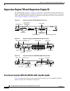
Route Switch Processor 720
(RSP720-10GE)
• Slots 1 and 2 (3-slot enhanced [-S] chassis
and 4-slot chassis)
• Slots 5 and 6 (6-slot and 9-slot enhanced [-S]
chassis and 9-slot chassis)
• Not supported in the 3-slot, 6-slot, or 13-slot
chassis
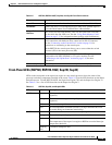
Route Switch Processor 720
(RSP720)
• Slots 1 and 2 (4-slot chassis)
• Slots 5 and 6 (6-slot and 9-slot chassis,
including enhanced [-S] chassis)
• Slots 7 and 8 (13-slot chassis)
• Not supported in the 3-slot chassis
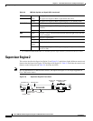
Supervisor Engine 720
(Sup720)
• Slots 1 and 2 (3-slot and 4-slot chassis)
• Slots 5 and 6 (6-slot and 9-slot chassis)
• Slots 7 and 8 (13-slot chassis)