


3-10
Cisco 7600 Series Router Supervisor Engine and Route Switch Processor Guide
OL-10100-04
Chapter 3 Installing and Configuring Route Switch Processors and Supervisor Engines
Connecting to the Uplink Ports
Supervisor Engine 2
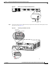
In addition to the above configuration requirements, note that with a Supervisor Engine 2 you can use
two types of console cables to connect a terminal to the console port. To accommodate either type of
cable, set the console port mode switch (to the right of the console port) as follows:
• To use the RJ-45-to-RJ-45 rollover cable and DTE adapter (labeled “Terminal”) provided with the
router, make sure that the console port mode switch is in the in position (factory default).
• To use a Catalyst 5000 Supervisor Engine III console cable and adapter (not provided), make sure
that the console port mode switch is in the out position, and use the appropriate adapter for the
terminal connection. See the
“Console Port Mode 2 Signaling and Pinouts (Sup2 Only)” section on
page B-10 for a list of console port pinouts when the switch is in the out position.
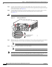
Note To access the console port mode switch, use a ballpoint pen tip or other small, pointed object.
Connecting a Modem
To connect a modem to the console port, observe the following guidelines:
• Use the RJ-45-to-RJ-45 rollover cable and the RJ-45-to-DB-25 data communications equipment
(DCE) adapter (labeled “Modem”) provided with the router.
• On a Supervisor Engine 2, make sure that the console port mode switch is in the in position (factory
default).
Connecting to the Uplink Ports
The supervisor engine and route switch processor have uplink ports that you use to connect the router to
other network devices. You can configure the ports with small form-factor pluggable (SFP), XENPAK,
X2, or Gigabit Interface Converter (GBIC) optics modules.
Table 3-2 lists the different types of uplink ports on each module. SFP, XENPAK, and X2 optics modules
have SC, LC, or MT-RJ connectors. GBIC modules (on the Supervisor Engine 2) have SC connectors.
Warning
Invisible laser radiation may be emitted from disconnected fibers or connectors. Do not stare into
beams or view directly with optical instruments.
Statement 1051
Caution Do not remove the plugs from the optical bores on the fiber-optic cable or the module port or until you
are ready to connect the cable. The plugs protect the optical bores and cable from contamination.