


2-15
Cisco 7600 Series Router Supervisor Engine and Route Switch Processor Guide
OL-10100-04
Chapter 2 Route Switch Processors and Supervisor Engines
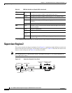
Supervisor Engine 2
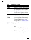
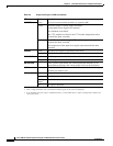
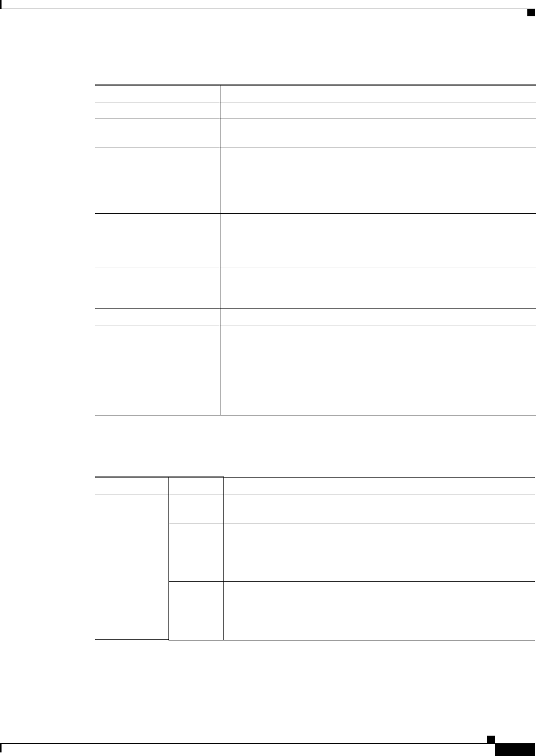
Table 2-5 lists the LED functions on the Supervisor Engine 2.
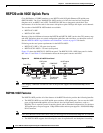
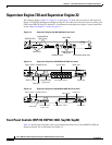
Tab le 2-4 Supervisor Engine 2 Front-Panel Controls
Component Description
Status LEDs
Indicate the status of various functions on the module (see Table 2-5).
Reset Button
Restarts the router. Use a ballpoint pen tip or other small, pointed object
to access the Reset button.
Console Port
Provides access to the router either locally (with a console terminal) or
remotely (with a modem). The port is an EIA/TIA-232 asynchronous,
serial connection with hardware flow control and an RJ-45 connector. See
the
“Connecting to the Console Port” section on page 3-9 for instructions
on connecting to the console port.
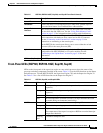
Console Port Mode Switch
Enables you to connect a terminal to the console port using either the
cable and adapters provided with the router (switch in the in position,
factory default) or a Catalyst 5000 Supervisor Engine III console cable
and adapter, not provided (switch in the out position).
PCMCIA Slot and LED
PCMCIA flash memory card slot. Do not remove the card from the slot
while the disk LED is on. See the
“Using Flash Memory Cards” section
on page 3-12 for information about working with flash memory.
Switch Load Meter
A visual approximation of the current traffic load across the backplane.
Uplink Ports
Used to connect the router to another network device. Two dual-port
Gigabit Ethernet uplink ports operate in full-duplex mode only. You can
configure the ports with any combination of copper, short-wave (SX),
long-wave/long-haul (LX/LH), extended-reach (ZX), and coarse
wavelength division multiplexing (CWDM) 1000BASE-X Gigabit
Interface Converters (GBICs). See the
“Connecting to the Uplink Ports”
section on page 3-10 for more information.
Tab le 2-5 Supervisor Engine 2 LEDs
LED Color Description
STATUS
Green All diagnostics pass; the module is operational (normal initialization
sequence).
Orange The module is booting or running diagnostics (normal initialization
sequence).
An overtemperature condition has occurred. (A minor threshold has
been exceeded during environmental monitoring.)
Red Diagnostic test failed; the module is not operational. (The fault occurred
during the initialization sequence.)
An overtemperature condition has occurred. (A major threshold has
been exceeded during environmental monitoring.)