


B-7
Cisco 7600 Series Router Supervisor Engine and Route Switch Processor Guide
OL-10100-04
Appendix B Cable and Connector Specifications
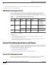
Console Port Cabling Specifications and Pinouts
The accessories kit that is shipped with your router contains the necessary cable and adapters to connect
a terminal or modem to the front-panel console port.
Console Port Signals and Pinouts
The Cisco 7600 series router is shipped with an accessories kit that contains the cable and adapters you
need to connect a console (an ASCII terminal or PC running terminal emulation software) or modem to
the console port on the front panel of the supervisor engine or route switch processor. For information
about the signals and pinouts for the Supervisor Engine 2 console port in mode 2, see the
“Console Port
Mode 2 Signaling and Pinouts (Sup2 Only)” section on page B-10.
The accessories kit includes these items:
• RJ-45-to-RJ-45 rollover cable
• RJ-45-to-DB-9 female DTE adapter (labeled “Terminal”)
• RJ-45-to-DB-25 female DTE adapter (labeled “Terminal”)
• RJ-45-to-DB-25 male DCE adapter (labeled “Modem”)
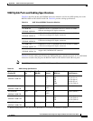
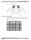
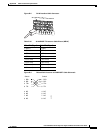
Identifying a Rollover Cable
You can identify a rollover cable by comparing the two ends of the cable. Holding the cables
side-by-side, with the tab at the back, the wire connected to the pin on the outside of the left plug should
be the same color as the wire connected to the pin on the outside of the right plug. (See
Figure B-1.) If
you purchased your cable from Cisco Systems, pin 1 is white on one connector, and pin 8 is white on the
other (a rollover cable reverses pins 1 and 8, 2 and 7, 3 and 6, and 4 and 5).
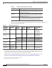
Tab le B-7 EIA/TIA-232 Transmission Speed Versus Distance
Rate (bps) Distance (feet) Distance (meters)
2400 200 60
4800 100 30
9600 50 15
19,200 25 7.6
38,400 12 3.7
56,000 8.6 2.6