


Index
IN-2
Cisco 7600 Series Router Supervisor Engine and Route Switch Processor Guide
OL-10100-04
D
DB-25 adapter B-9
DB-9 adapter B-8
DISK LED, Sup Eng 720, Sup Eng 32 2-14
DRAM, default 1-4
E
EEPROM 1-4, 1-6
EIA/TIA-232 transmission speeds B-7
environmental monitoring 3-14
environmental specifications (table) A-1
ESD, preventing damage 3-2
excessive link spans B-16
F
fault tolerance and redundancy 1-3
fiber optics
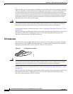
cleaning B-15
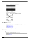
connectors B-12
filler plate, module 3-6, 3-7
flash memory cards 3-12, 3-13, 3-14
front panel
console port mode switch 3-10
disk slots 3-12
LEDs 2-13
Reset button 2-13
Sup2 (figure) 2-14
uplink ports 2-13
front panel controls 2-13
RSP720, Sup720, Sup32 2-13
Sup2 2-15
G
GBICs, connecting to 3-10
Gigabit Ethernet cables B-4, B-5, B-6
H
hot swapping
Cisco 7600 series router components 1-4
modules 3-8
supervisor engines and RSPs 3-8
I
installing
flash memory cards 3-13
modules 3-4
patch cord B-17
interfaces, addresses of 1-5
L
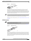
LC connectors B-14
LEDs
ACTIVE 2-14
CONSOLE 2-16
DISK (Sup Eng 720, Sup Eng 32 only) 2-14
front panel 2-13
LINK 2-14, 2-16
PCMCIA (Sup Eng 2 only) 2-16
PWR MGMT 2-14, 2-16
RSP720, Sup720, Sup32 2-13
STATUS 2-13, 2-15
Sup2 2-15
SWITCH LOAD (Sup Eng 2 only) 2-16
SYSTEM 2-13, 2-16