


3-4
Cisco 7600 Series Router Supervisor Engine and Route Switch Processor Guide
OL-10100-04
Chapter 3 Installing and Configuring Route Switch Processors and Supervisor Engines
Installing a Supervisor Engine or Route Switch Processor
Installing a Supervisor Engine or Route Switch Processor
To install a supervisor engine or route switch processor module in the router, perform the following
steps:
Caution To prevent ESD damage, handle modules by the carrier edges only.
Step 1 Choose a slot for the module (see Table 3-1). Make sure that there is enough clearance to accommodate
any equipment that will be connected to the ports on the module. If possible, place modules between
empty slots that contain only blank module filler plates.
a. If a blank module filler plate is installed in the slot in which you plan to install the module, remove
the plate by removing its two Phillips pan-head screws.
b. If another module is installed in the slot, remove the module by following the procedure in the
“Removing a Supervisor Engine or Route Switch Processor” section on page 3-7.
Step 2 Verify that the captive installation screws are tightened on all of the modules installed in the chassis.
This step ensures that the EMI gaskets on all modules are fully compressed in order to maximize the
opening space for the new or replacement module.
Note If the captive installation screws are loose, the EMI gaskets on the installed modules will push
adjacent modules toward the open slot, which reduces the opening size and makes it difficult to
install the new module.
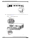
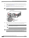
Step 3 Fully open both ejector levers on the new module. (See Figure 3-1.)
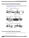
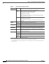
Supervisor Engine 32 • Slots 1 and 2 (4-slot chassis)
• Slots 5 and 6 (6-slot and 9-slot chassis)
• Slots 7 and 8 (13-slot chassis)
• Not supported in the 3-slot chassis
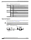
Supervisor Engine 2 • Slots 1 and 2 (all chassis)
• Not supported in the 4-slot chassis
Table 3-1 Supervisor Engine and Route Switch Processor Slot Assignments (continued)
Module Slot Assignments