


C-4
Cisco 3600 Series Routers Hardware Installation Guide
OL-2056-05
Appendix C Configuration Register
Configuring the Boot Field
Configuring the Boot Field
The lowest four bits of the configuration register (bits 3, 2, 1, and 0) form the boot field. (See Table C-2.)
The boot field specifies a number in binary form. If you set the boot field value to 0, you must have
console port access to boot the operating system manually. Refer to the boot command in the “ROM
Monitor Command Descriptions” section on page B-4.
If you set the boot field to a value of 2 to F, and there is a valid boot system command stored in the
configuration file, the router software processes each boot command in sequence until the process is
successful or the end of the list is reached. If there are no boot commands in the configuration file, the
router attempts to boot the first file in Flash memory.
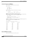
In the following example, the configuration register is set to boot the router automatically from Flash
memory and to ignore Break at the next reboot of the router:
Router# configure terminal
Enter configuration commands, one per line.
Edit with DELETE, CTRL/W, and CTRL/U; end with CTRL/Z
config-register 0x102
Ctrl-z
Note A boot system command in the router configuration in NVRAM overrides booting from Flash memory.
Bit 8 controls the console Break key. Setting bit 8 (the factory default) causes the processor to ignore the
console Break key. Clearing bit 8 causes the processor to interpret Break as a command to force the
router into the bootstrap monitor, halting normal operation. Break can always be sent in the first
60 seconds while the router is rebooting, regardless of the configuration settings.
Bit 9 controls the system boot. Clearing bit 9 (the factory default) causes the system to boot from Flash
memory. Clearing bit 9 causes the system to use the secondary bootstrap (netbooting). This is typically
not used.
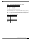
Bit 10 controls the host portion of the IP broadcast address. Setting bit 10 causes the processor to use all
zeros; clearing bit 10 (the factory default) causes the processor to use all ones. Bit 10 interacts with bit
14, which controls the network and subnet portions of the broadcast address. Table C-3 shows the
combined effect of bits 10 and 14.
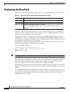
Table C-2 Explanation of Boot Field Configuration Register Bits (00-03)
Boot Field Meaning
00 Stays at the ROM monitor on a reload or power cycle
01 Boots the first image in Flash image as a system image
02-F Enables default booting from Flash memory
Enables boot system commands that override default booting from Flash
memory