


3-20
Cisco 3600 Series Routers Hardware Installation Guide
OL-2056-05
Chapter 3 Installing the Router
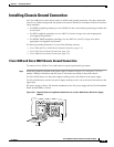
Installing Chassis Ground Connection
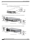
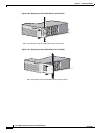
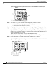
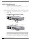
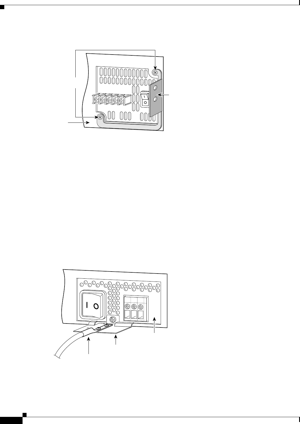
Figure 3-32 Required Ground-Lug Bracket Attachment on a Cisco 3640 Router (DC Power Supply
Shown)
Step 2
Strip one end of the ground wire to the length required for the ground lug or terminal.
–
For the NEBS ground lug—approximately 0.75 in. (20 mm)
–
For user-provided ring terminal—as required
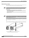
Step 3 Crimp the ground wire to the ground lug or ring terminal, using a crimp tool of the appropriate size.
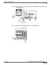
Step 4 Attach the ground lug to the ground-lug bracket as shown in Figure 3-33, Figure 3-34, or Figure 3-35,
or attach the ring terminal to the ground-lug bracket as shown in Figure 3-36, Figure 3-37, or
Figure 3-38. For the ground lug, use the two screws with captive locking washers provided. For a ring
terminal, use one of the screws provided. Use a number 2 Phillips screwdriver, and tighten the screws to
a torque of 8 to 10 in-lb (0.9 to 1.1 N-m).
Where a DC power supply is shown, AC power supply attachment is similar.
Diagonal attachment of the ground lug to the bracket provides clearance for the RPS power cable.
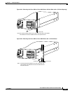
Step 5 Connect the other end of the ground wire to a suitable grounding point at your site.
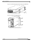
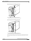
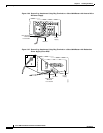
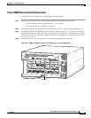
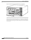
Figure 3-33 NEBS-Compliant Ground Lug Attachment on a Cisco 3620 Router with Internal AC or DC
Power Supply
15846
Power
supply
Bracket
Mounting
screws
Bracket
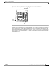
Ground lug mounted
on a Cisco 3620 router
without Cisco RPS
15850
Power
supply