


3-31
Cisco 3600 Series Routers Hardware Installation Guide
OL-2056-05
Chapter 3 Installing the Router
Power Connections
Warning
When stranded wiring is required, use approved wiring terminations, such as closed-loop or
spade-type with upturned lugs. These terminations should be the appropriate size for the wires and
should clamp both the insulation and conductor.
Statement 1002
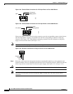
Step 4 Remove the plastic covers from the terminal block. Save them for reinstallation after you finish wiring.
Note Do not remove the colored screw at either end of the terminal block. Those are the terminal mounting
screws.
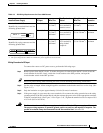
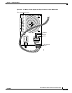
Step 5 Connect the DC power input wires to the terminal block as shown in Figure 3-45 or Figure 3-46. To
avoid interference with the on/off switches, and to bring the wires close to the cable-tie attachment point,
organize the wires downward from the terminal block.
Warning
The illustration shows the DC power supply terminal block. Wire the DC power supply as illustrated.
The proper wiring sequence is ground to ground, positive to positive, and negative to negative. The
ground wire should always be connected first and disconnected last.
Statement 239
Caution Do not overtorque the terminal block contact screws. Recommended torque is 8.0 ± 0.5 in-lb
(0.93 ±0.05 N-m).
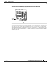
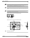
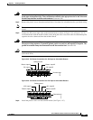
Figure 3-45 DC Power Connections for –DC Input to Cisco 3631 Routers
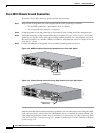
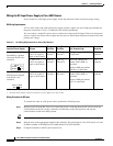
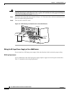
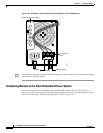
Figure 3-46 DC Power Connections for +DC Input to Cisco 3631 Routers
Step 6
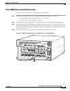
Install the plastic covers over the terminal block. (See Figure 3-47.)
88135
Safety ground
Terminal strip
A
+
B
+
Return, input A
-DC, input A
Return, input B
-DC, input B
88136
Safety ground
Terminal strip
A
+
B
+
+DC, input A
Return, input A
+DC, input B
Return, input B