


3-34
Cisco 3600 Series Routers Hardware Installation Guide
OL-2056-05
Chapter 3 Installing the Router
Power Connections
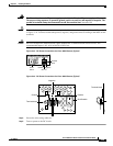
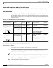
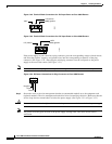
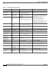
Figure 3-48 Terminal Block Connections for –DC Input Power to Cisco 3660 Routers
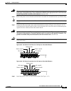
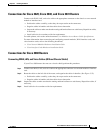
Figure 3-49 Terminal Block Connections for +DC Input Power to Cisco 3660 Routers
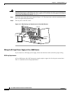
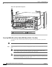
If the power supply in your router has a plug connector, press the corresponding orange-colored release,
and insert the positive, negative, and ground wires into the corresponding receptacles of the plug
connector. (See Figure 3-50.) Then plug the wired plug connector into the receptacle on the power
supply at the rear of the router. (See Figure 3-51.)
Note To remove wires from a plug connector, press the orange-colored release next to each receptacle.
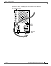
Figure 3-50 DC Power Connections for Plug Connector to Cisco 3660 Routers
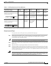
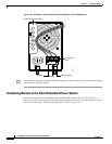
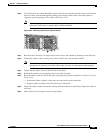
Step 5 Secure the wires to the wire management bracket (recommended method) or to the equipment rack
(optional method). The wire management bracket has holes for attaching cable ties. Make sure that the
service loop does not extend above or below the power supply. (See Figure 3-51 or Figure 3-52.)
Caution Power wires must exit to the right, and the service loop must not extend above or below the power supply.
Note The power wires may pass in front of the power supply cooling vents. The wires do not restrict
ventilation.
82493
0 V (return)
+
-48 V
Safety ground
72838
+48 V
+
0 V (return)
Safety ground
Negative
Ground
Positive
18699