


3-33
Cisco 3600 Series Routers Hardware Installation Guide
OL-2056-05
Chapter 3 Installing the Router
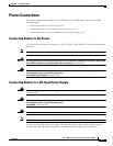
Power Connections
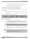
Wiring Procedure for DC Input
To connect the router to a DC power source, perform the following steps:
Step 1 Remove power from the DC circuit. To ensure that power is removed from the DC circuit, locate the
circuit breaker for the DC circuit, switch the circuit breaker to the OFF position, and tape the
circuit-breaker switch in the OFF position.
Tip Secure all power cabling when installing this unit to avoid disturbing field-wiring connections.
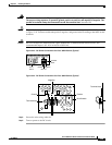
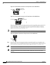
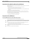
Step 2 Cut the wires to length. Allow enough length for attachment to the bracket and for a service loop. (See
Figure 3-47.)
Step 3 Strip the insulation to expose approximately 0.4 inch (10 mm) of conductor.
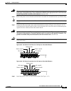
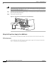
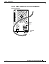
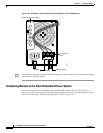
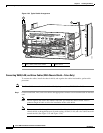
Step 4 If the power supply in your router has screw terminals, first connect the safety ground wire to the safety
ground terminal of the DC terminal block, and then connect the power wires to the appropriate terminals
of the DC terminal block. (See Figure 3-48 or Figure 3-49.) Tighten the terminal screw to a torque of 8.0
± 0.5 in-lb (0.93 ± 0.05 N-m).
Warning
The illustration shows the DC power supply terminal block. Wire the DC power supply as illustrated.
The proper wiring sequence is ground to ground, positive to positive, and negative to negative. The
ground wire should always be connected first and disconnected last.
Statement 239
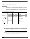
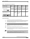
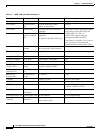
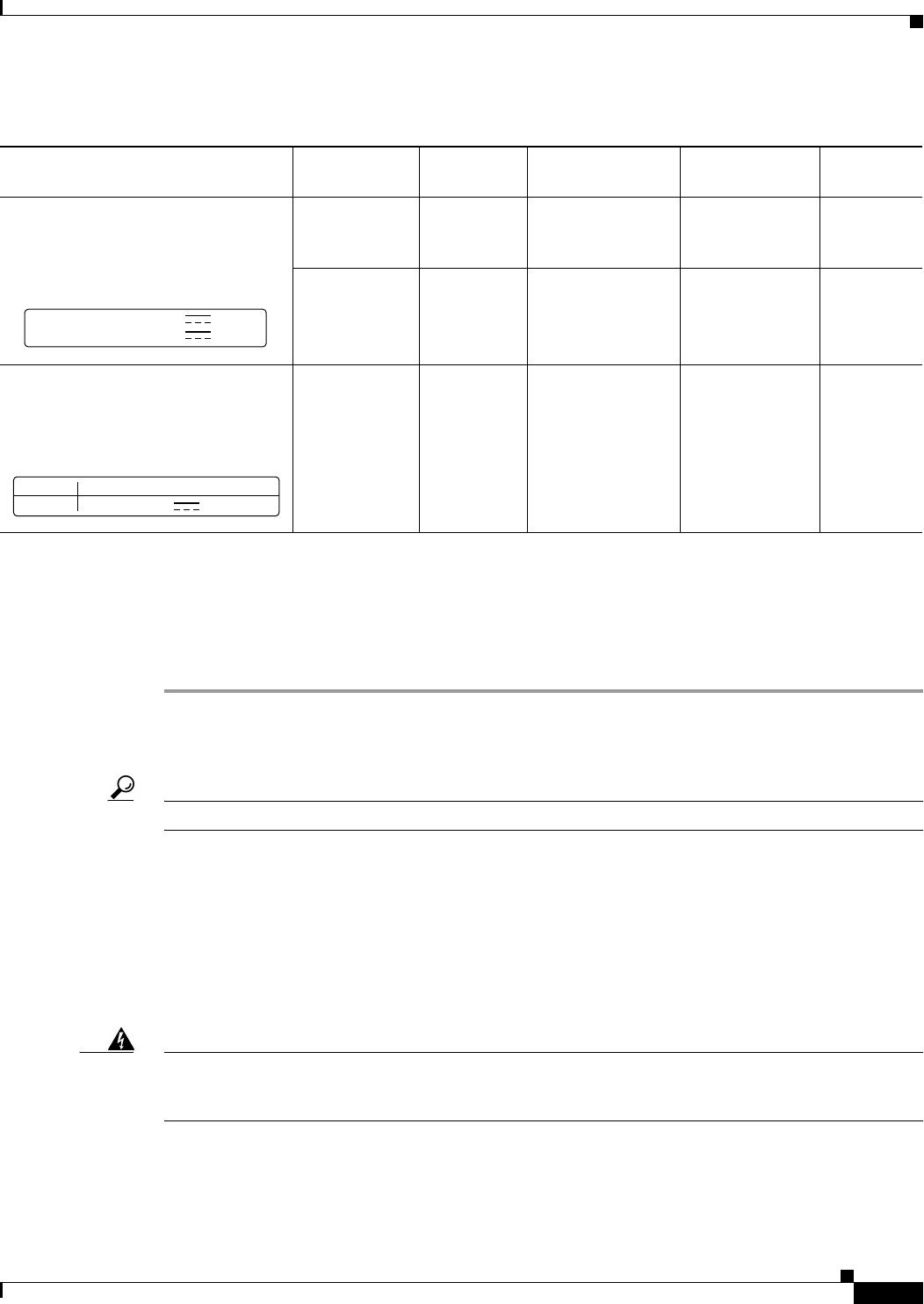
Table 3-3 DC Wiring Requirements for Cisco 3660 Routers
Installed Power Supply DC Input Wire Size
Wire Termination
Method
Safety Ground
Wire Size
Overcurrent
Protection
Nominal 24/48 VDC
1
Identified by a terminal block and the
following printed label:
1. The input voltage tolerance limits for nominal 24/48-V power supplies are 18 and 72 VDC.
24 - 36 V, 16 A AWG 12
(3.0 mm
2
)
Terminal block;
wires retained by
retention screws
AWG 12
(3.0 mm
2
)
20 A
maximum
36 - 60 V, 7 A AWG 14
(2.0 mm
2
),
minimum
Terminal block;
wires retained by
retention screws
AWG 12 or 14
(3.0 or 2.0 mm
2
)
15 A
maximum
Nominal 48 VDC
2
Identified by a plug connector and the
following printed label:
2. The input voltage tolerance limits for nominal 48-V power supplies are 38 and 72 VDC.
48 - 60 V, 8 A AWG 14
(2.0 mm
2
),
minimum
Plug connector;
wires retained by
spring-loaded
receptacle
AWG 12 or 14
(3.0 or 2.0 mm
2
)
15 A
maximum
INPUT +/-
24-36V
36-60V
16A
7A
100-240V~, 4-2A, 50/60 Hz
-48V to -60V
AC PS
DC PS , 8A